Distributing valve for concrete pump and the concrete pump

a technology of concrete pump and distributing valve, which is applied in the direction of pump, positive displacement liquid engine, machine/engine, etc., can solve the problems of gate-type distributing valve not meeting the requirement, affecting the sucking performance of concrete pump, and limited concrete slurry pressure in the delivery pipe, etc., to achieve simple structure, long service life, and high reliability

Inactive Publication Date: 2015-11-17
HUNAN SANY INTELLIGENT CONTROL EQUIP +1
View PDF11 Cites 0 Cited by
  • Summary
  • Abstract
  • Description
  • Claims
  • Application Information

AI Technical Summary

Benefits of technology

[0013]In view of the defects of the concrete distributing valve mentioned above, the first aspect of the present invention is to provide a distributing valve for a concrete pump which has simple structure, high reliability, long service life and low production costs so as to reduce power consumption and keep a good material sucking performance while meeting the requirement for pumping concrete slurry at a high pressure.
[0020]Furthermore, there is a smooth transition between the first pipe section and the second pipe section.
[0025]Compared with the prior art, the distributing valve for a concrete pump according to the present invention is located at a predetermined position outside of the hopper. The valve core includes a first pipe section and a second pipe section, the first pipe section extends vertically, and its outer wall surface is rotatably connected to the hole wall surface of the valve body; the second pipe section extends transversely in the delivering cavity and its inner end is connected to the lower end of the first pipe section, and a revolution fitting surface is formed between the end face of the outer end of the second pipe section and the inner wall surface of the delivering cavity. Thus, an L-shaped pipe is formed by the first pipe section and the second pipe section of the valve core, and the first pipe section is rotatably connected with the valve body, and a revolution fitting surface is formed between the outer end of the second pipe section and the inner wall surface of the delivering cavity. Compared with the distributing valve in the prior art CN1012445866A, the sealing arrangement is only provided above the valve body and no revolution fitting step face is needed; thereby the structure of the distributing valve for a concrete pump is simplified greatly, so as to make the manufacturing of the distributing valve more easily and simply, and improve the working reliability of the distributing valve, and reduce its manufacturing cost; due to the absence of the step face, the useful-life of sealing between the valve body and the valve core may be increased and sealing is ensured, the maintenance period of the distributing valve is increased and thereby the serve life of the distribution valve is also prolonged; as the fitting surface between the valve core and the valve body is reduced, and the friction force between them is reduced as well, thereby the power required by the rotation of the valve core may be decreased and the power consumption of the distributing valve for a concrete pump will be reduced. In addition, the fitting between the first and second pipe sections and the valve body is respectively seal fitting, therefore, it can meet the demand of delivering concrete slurry at high pressure while retaining fine suction capability.
[0026]In a further preferred technical solution, the valve body also includes a second material suction opening communicating with another delivery cylinder. In the first position, while one delivery cylinder suck material through the valve core, the second material suction opening is communicated with the material outlet, and another delivery cylinder in communication with the second material suction opening can pump the concrete slurry that is sucked in the former phase through the delivering cavity; in the second position, while one delivery cylinder pumps material, the valve core is communicated with the second material suction opening, now another delivery cylinder may suck material via the valve core to prepare for the next phase of pumping material. By means of the distributing valve according to this technical solution, the concrete pump can pump concrete slurry to outside at relatively higher frequency so that the pumping efficiency of the concrete pump is increased.
[0027]In a further preferred technical solution, a spring means is mounted between the clamp ring of the second pipe section and the second pipe section body, so that a close fitting of the revolution fitting surface between the clamp ring and the wear resistant plate can be kept and a good separation between the inner chamber of the valve core and the delivery cavity is ensured, thereby the demand of delivering concrete slurry at high pressure is met better.
[0028]In a further preferred technical solution, the intersection line of the fitting surface and the reference plane is an outer convex arc, so that the revolution fitting surface forms a structure with an outer convex middle portion and an inwardly extending periphery portion. This structure can be automatically aligned and keep sealed when the second pipe section fits the inner wall surface of the valve body; and this structure also enable the valve body to provide a certain supporting force for the valve core so as to improve the working stability and reliability of the distributing valve.

Problems solved by technology

However, the disadvantage of the gate-type distributing valve is that the pressure of the concrete slurry in the delivery pipe is limited by the fitting position of the periphery of the gate since the position between the delivery cylinder and the delivery pipe is realized by switching the gates positions.
Thus the gate-type distributing valve can not meet the requirement of pumping concrete slurry at a high pressure.
However, the disadvantage of the S-type distributing valve is that the S-type bend pipe of the S-type distributing valve is located in the hopper 110 and occupies a part of volume of the hopper 110, so as badly affects the flowing of concrete slurry, thus affecting the sucking performance of the concrete pump.
The C-type distributing valve and the skirt valve have the similar working principle as the S-type distributing valve, and thus have the same defects.
The above said configuration makes the distribution valve have very complex structure, therefore it leads to complex and difficult production process, and it is difficult to ensure the operation reliability of the distribution valve.
Furthermore, the valve core can move up and down, the fit clearance of any step surface of the distribution valve can be embodied in the fit clearance of another step surface, so that the upper and lower two step surfaces will enlarge the fit clearance between the valve body and the valve core, decrease the sealing useful-life between the valve body and the valve core and thereby decrease the serve life of the distribution valve.
As the upper extension shaft and the lower extension shaft are rotatably connected to the valve body respectively, the complex structure and the sealing requirement make the rotation fit surface relatively large between the valve body and the valve core, so that the power required by the state switching of the distribution valve is increased, and thereby the power consumption of the concrete pump vehicle is increased.

Method used


Image

  • Distributing valve for concrete pump and the concrete pump
  • Distributing valve for concrete pump and the concrete pump
  • Distributing valve for concrete pump and the concrete pump

Examples


Embodiment Construction

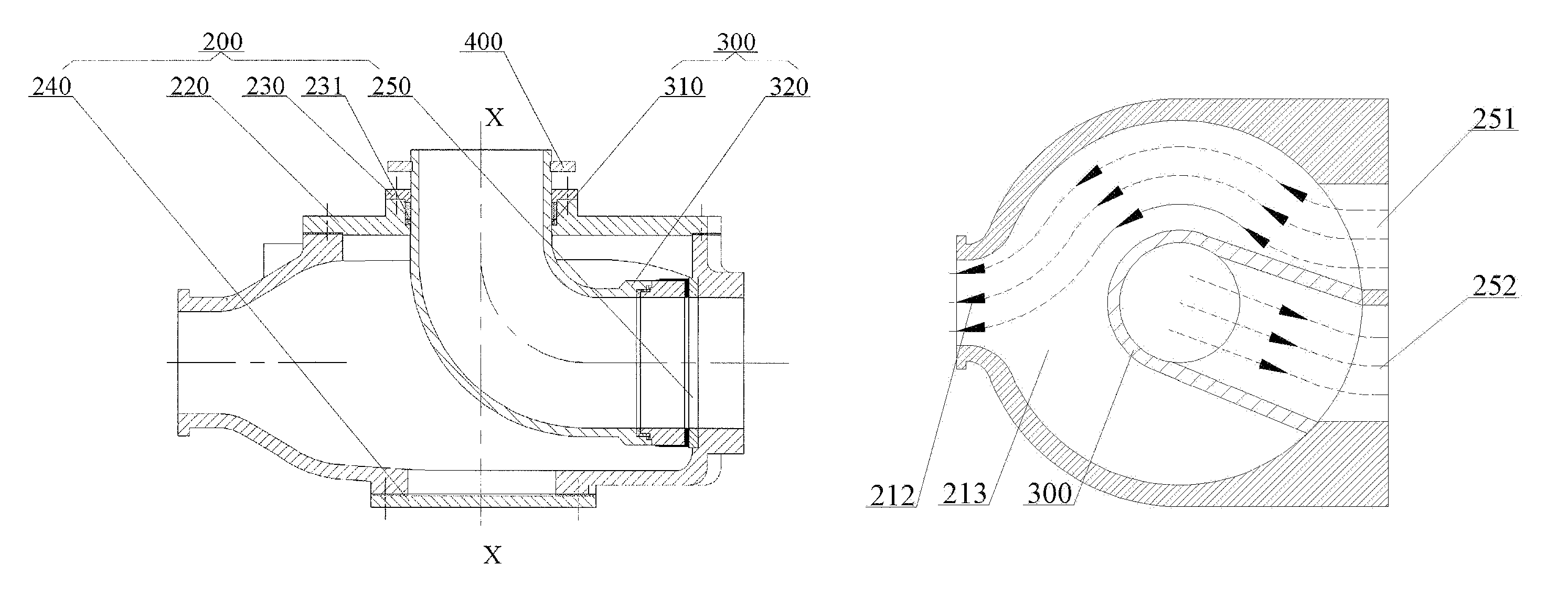
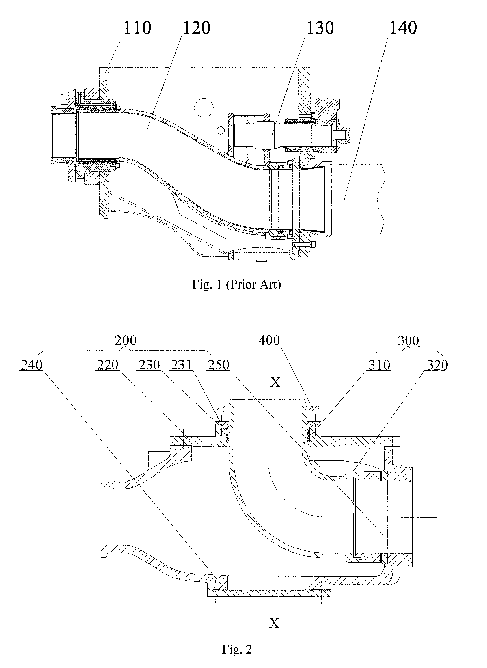
[0043]In order to ensure the sealing performance of the delivery cavity and meet the demand of delivering concrete slurry at a high pressure, it is designed a complex sealing structure in the prior art to improve and ensure the sealing performance of the delivery cavity. The core of the present invention lies in overcoming the technical prejudice of realizing the sealing performance of the delivery cavity via a sealing structure in the prior art, and providing a distributing valve for a concrete pump of a simple structure, high reliability, long service life and low manufacturing cost by changing the structure of the distributing valve, thereby realizing the object of the present invention.

[0044]The present invention will be described in detail hereinafter in conjunction with the drawings. The description in this section is only illustrative and explanatory, and should not be considered to limit the protection scope of the present invention. It should be noted that although technica...


PUM

PropertyMeasurementUnit
suctionaaaaaaaaaa
reciprocating movementsaaaaaaaaaa
time periodaaaaaaaaaa

Abstract

A distributing valve for a concrete pump and the concrete pump are provided, the distributing valve comprises a valve body (200) and a valve core (300), and a delivering cavity (213) is internally formed in the valve body (200) and is provided with a material inlet, a material outlet (212) and material suction openings (251,252). The material outlet (212) is communicated with a delivery pipe and the material suction opening (251,252) is communicated with a delivery cylinder (500). The valve core (300) is a L-shaped pipe formed by a first pipe section (310) and a second pipe section (320), and one end of the L-shaped pipe is connected with a hopper (600) and a revolution fitting surface is formed between the end face of the other end of the L-shaped pipe and the internal face of the valve body (200).

Description

CROSS-REFERENCE TO RELATED APPLICATIONS[0001]This application is the U.S. national stage application of International Patent Application No. PCT / CN2011 / 072962, filed Apr. 18, 2011, which claims priority to Chinese Patent Application No. 201010164558.5, filed Apr. 16, 2010, the disclosures of each of which are incorporated herein by reference in their entirety.REFERENCE APPLICATION[0002]This application claims the priority of Chinese Patent Application No. 201010164558.5, entitled “DISTRIBUTING VALVE FOR CONCRETE PUMP, AND CONCRETE PUMP” filed on Apr. 16, 2010 with State Intellectual Property Office of PRC.FIELD OF THE INVENTION[0003]The present invention relates to a concrete pump technique, in particular to a distributing valve for concrete pump and to a concrete pump with this distributing valve.BACKGROUND OF THE INVENTION[0004]A concrete pump is one of widely used concrete machinery presently. The concrete pump generally includes a hopper, a delivery cylinder, a distributing valv...

Claims


Application Information

Patent Timeline
Patent Type & Authority Patents(United States)
IPC IPC(8): F04B15/00F04B15/02F04B7/00F04B11/00
CPCF04B15/023F04B7/008F04B7/0034F04B11/005Y10S417/90
Inventor YI, XIAOGANGZHU, HONGLI, LIANGRONG
Owner HUNAN SANY INTELLIGENT CONTROL EQUIP
Why Eureka
Try Eureka