Gas dispersion nozzle for a fire arm silencer

a technology of gas dispersion nozzle and firearm silencer, which is applied in the direction of muzzle attachment, weapon components, weapons, etc., can solve the problems of reducing the flow rate of propellant gases, and achieve the reduction or elimination of report and/or flash, small size and easy manufacturing

Active Publication Date: 2015-11-17
WHITE MARK
View PDF17 Cites 13 Cited by
  • Summary
  • Abstract
  • Description
  • Claims
  • Application Information

AI Technical Summary

Benefits of technology

[0008]The present invention is a gas dispersion nozzle for a gun silencer having a nozzle portion with a front end and a rear end and walls enclosing a hollow interior therein through which a projectile and propellant gases pass. The rear end of the nozzle portion has a base portion attached thereto constructed to attach the nozzle portion to the gun silencer and to extend the nozzle portion into an interior of said gun silencer. The base portion is also constructed to attach the nozzle portion to a barrel of a firearm. The base portion has walls enclosing a hollow interior therein through which a projectile and propellant gases pass. The walls of the nozzle portion having channels which direct the flow of the propellant gases out of the hollow interior of the nozzle portion at an angle to a path along which the projectile passes. These channels in the nozzle portion cause the flow of the propellant gases to become turbulent or rotational or both, and they decrease the flow rate of the propellant gases. The nozzle portion may have an internal choke at the front end of the nozzle portion to direct the propellant gases into the channels of said nozzle portion. This nozzle portion decreases the report and / or flash produced by the discharge of a firearm as a result of the decrease in flow rate of propellant gases when they pass through the side channels in the nozzle portion.
[0009]In an alternant embodiment, the rear end of the nozzle portion has a threaded extension attached thereto which attaches the nozzle portion to a gun silencer and extends the nozzle portion into an interior of the gun silencer. The threaded extension also attaches the nozzle portion to a barrel of a firearm. The threaded extension allows extension of the nozzle portion into the interior of the gun silencer off center of the interior of said gun silencer, if desired. The walls of this nozzle portion also have channels which direct the flow of the propellant gases out of the hollow interior at an angle to a path along which said projectile passes and into the interior of the gun silencer. Accordingly, this nozzle portion causes turbulent or rotational flow of propellant gases and decreases the report and / or flash produced by the discharge of said firearm.
[0010]Preferably, the gas dispersion nozzle is attached at the rear end of its nozzle portion to a gun silencer in which the interior of the gun silencer has one or more slant baffles and one or more blast baffles. The blast baffle has angled grooves to cause the flow of the propellant gases to become rotational, thereby decreasing the flow rate of the propellant gases through the interior of the gun silencer. In this arrangement, when the gas dispersion nozzle is used with a gun silencer it can increase the efficiency of the gun silencer in reducing sound and flash by 20% to 60%. When the blast baffle, with angled grooves, is used with a gun silencer it can increase the efficiency of the gun silencer in reducing sound and flash by 10% to 40%. When both the gas dispersion nozzle and the blast baffle are used together with a gun silencer they can increase the efficiency of the gun silencer in reducing sound and flash by 30% to 90%. In addition, the combination of the gas dispersion nozzle and the blast baffle in the gun silencer can reduce the flow rate of propellant gases below the speed of sound as the propellant gases exit the front end of the silencer.

Problems solved by technology

These channels in the nozzle portion cause the flow of the propellant gases to become turbulent or rotational or both, and they decrease the flow rate of the propellant gases.

Method used


Image

  • Gas dispersion nozzle for a fire arm silencer
  • Gas dispersion nozzle for a fire arm silencer
  • Gas dispersion nozzle for a fire arm silencer

Examples


Embodiment Construction

[0027]While the following description details the preferred embodiments of the present invention, it is to be understood that the invention is not limited in its application to the details of construction and arrangement of the parts illustrated in the accompanying figures, since the invention is capable of other embodiments and of being practiced in various ways.

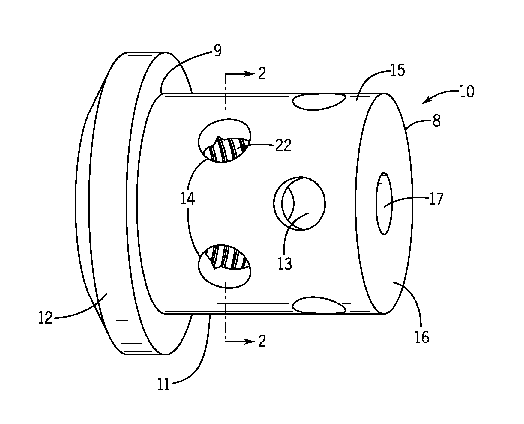
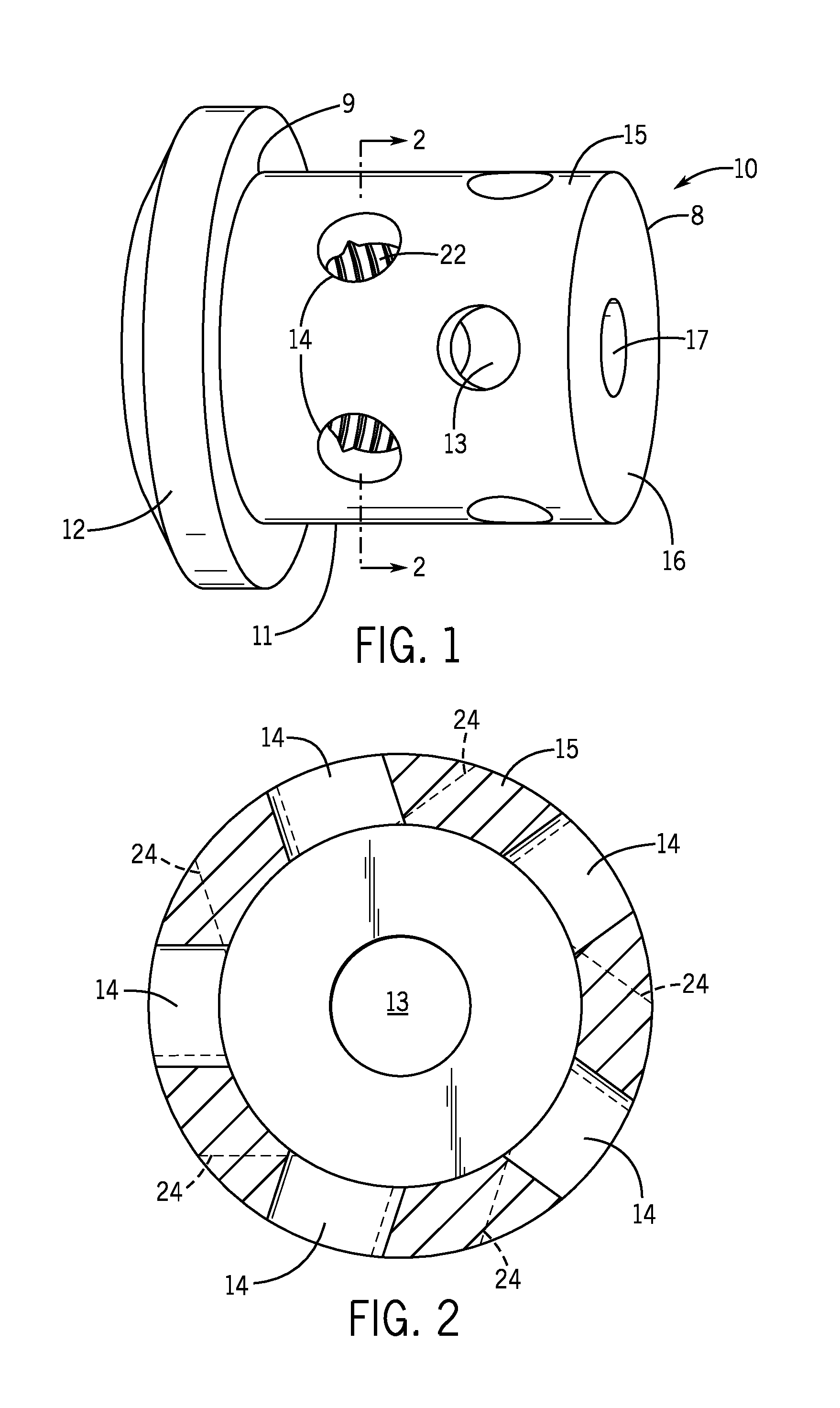
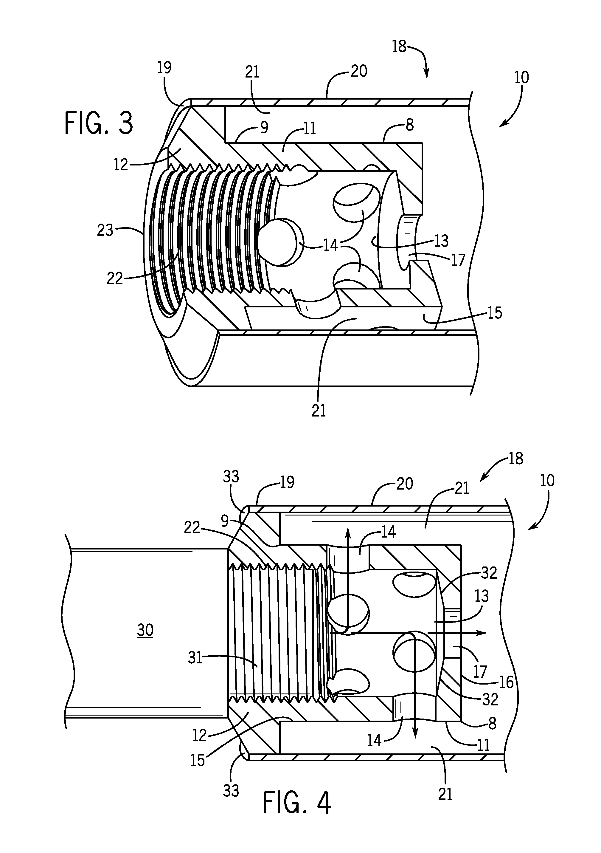
[0028]Gun silencers for self-loading pistols with moving barrels using Neilson adaptors (essentially vented or non-vented pistons that kick moving barrels into opening their actions to ensure reliable self-loading) are known; however, the use of the small fixed chamber of the present invention, placed at the muzzle of a firearm barrel for the purpose of redirecting propellant gases to the side, or in a volute curve, within the gun silencer chamber, are not known in the silencer industry.

[0029]Vent holes placed in the end of such a chamber can be directly perpendicular to a bullet's path, or they can be angled to induce a ro...


PUM


Abstract

A gas dispersion nozzle for a gun silencer having a nozzle portion with a front end and a rear end and walls enclosing a hollow interior therein. The rear end of the nozzle portion is attached to the gun silencer and the nozzle portion extends into the interior of the gun silencer. The rear end also attaches to a firearm. The walls have channels which direct flow of propellant gases out of the hollow interior and into the interior of the gun silencer at an angle to a path along which the projectile passes when the firearm is discharged. The channels cause the flow of propellant gases to become turbulent or rotational or both and can cause the flow rate of said propellant gases to decrease. The gas dispersion nozzle reduces the report and / or flash produced by the discharge of a firearm.

Description

CROSS REFERENCE TO RELATED APPLICATION[0001]This application claims the benefit of priority from U.S. nonprovisional patent application Ser. No. 13 / 772,206, filed Feb. 20, 2013.FIELD OF THE INVENTION[0002]The invention relates to firearm silencers and, more particularly, to a vented chamber or gas dispersion nozzle, placed between a firearm's barrel and a firearm silencer, to direct high-pressure propellant gases perpendicular to the firearm's bore, thereby adding greatly to the silencer's overall efficiency in reducing both the report and flash produced by the propellant gases.BACKGROUND OF THE INVENTION[0003]It is well known that when a firearm is discharged, jets of gas are formed within the barrel muzzle due to the expansion of gases upon detonation of the cartridge. Additionally, jets of gas are also formed as the bullet is propelled forward through the barrel, caused by the compression of gases in front of the bullet as it moves forward. Flash is caused by the incomplete combu...

Claims


Application Information

Patent Timeline
Patent Type & Authority Patents(United States)
IPC IPC(8): F41A21/30
CPCF41A21/30F41A21/34
Inventor WHITE, MARK
Owner WHITE MARK
Why Eureka
Try Eureka