Silencer for vacuum system of a wound drainage apparatus

a vacuum system and wound drainage technology, applied in the direction of suction pumps, other medical devices, intravenous devices, etc., can solve the problems of generating noise, significant irritation and discomfort of users or patients, and noise generation of commercial apparatus

Active Publication Date: 2015-11-24
SMITH & NEPHEW PLC
View PDF154 Cites 3 Cited by
  • Summary
  • Abstract
  • Description
  • Claims
  • Application Information

AI Technical Summary

Benefits of technology

[0015]It is an aim of embodiments of the present invention to provide portable apparatus for providing TNP therapy which is less noisy and produces less discomfort to a patient than known commercial apparatus.
[0046]The pressure control system may prevent the minimum pressure achieved from exceeding for example −200 mmHg so as not to cause undue patient discomfort. The pressure required may be set by the user at a number of discreet levels such as −50, −75, −100, −125, −150, −175 mmHg, for example, depending upon the needs of the wound in question and the advice of a clinician. Thus suitable pressure ranges in use may be from −25 to −80 mmHg, or −50 to −76 mmHg, or −50 to −75 mmHg as examples. The control system may also advantageously be able to maintain the set pressure within a tolerance band of + / −10 mmHg of the set point for 95% of the time the apparatus is operating given that leakage and exudation rates are within expected or normal levels.

Problems solved by technology

However, the above apparatus and methods are generally only applicable to a patient when hospitalised as the apparatus is complex, needing people having specialist knowledge in how to operate and maintain the apparatus, and also relatively heavy and bulky, not being adapted for easy mobility outside of a hospital environment by a patient, for example.
Such commercial apparatus are known to be noisy, partly in the interests of keeping weight to a minimum in portable apparatus.
However, airborne noise generated from diaphragm pumps , which are often used, is known to be a significant source of irritation and discomfort to the user or patient and also to people in the vicinity.
However, many different types of pump may be used including piston pumps, rotary vane pumps, turbo fan, for example, all generate noise.
The level of discomfort produced by airborne noise in such apparatus is not to be underestimated as it has been known for patients to turn the apparatus off to alleviate the discomfort with the consequent obvious disadvantages to wound healing.

Method used


Image

  • Silencer for vacuum system of a wound drainage apparatus
  • Silencer for vacuum system of a wound drainage apparatus
  • Silencer for vacuum system of a wound drainage apparatus

Examples


Embodiment Construction

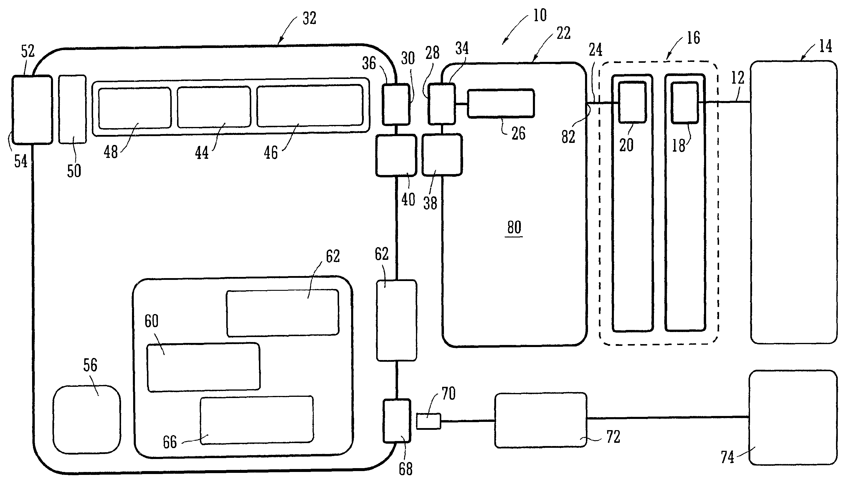
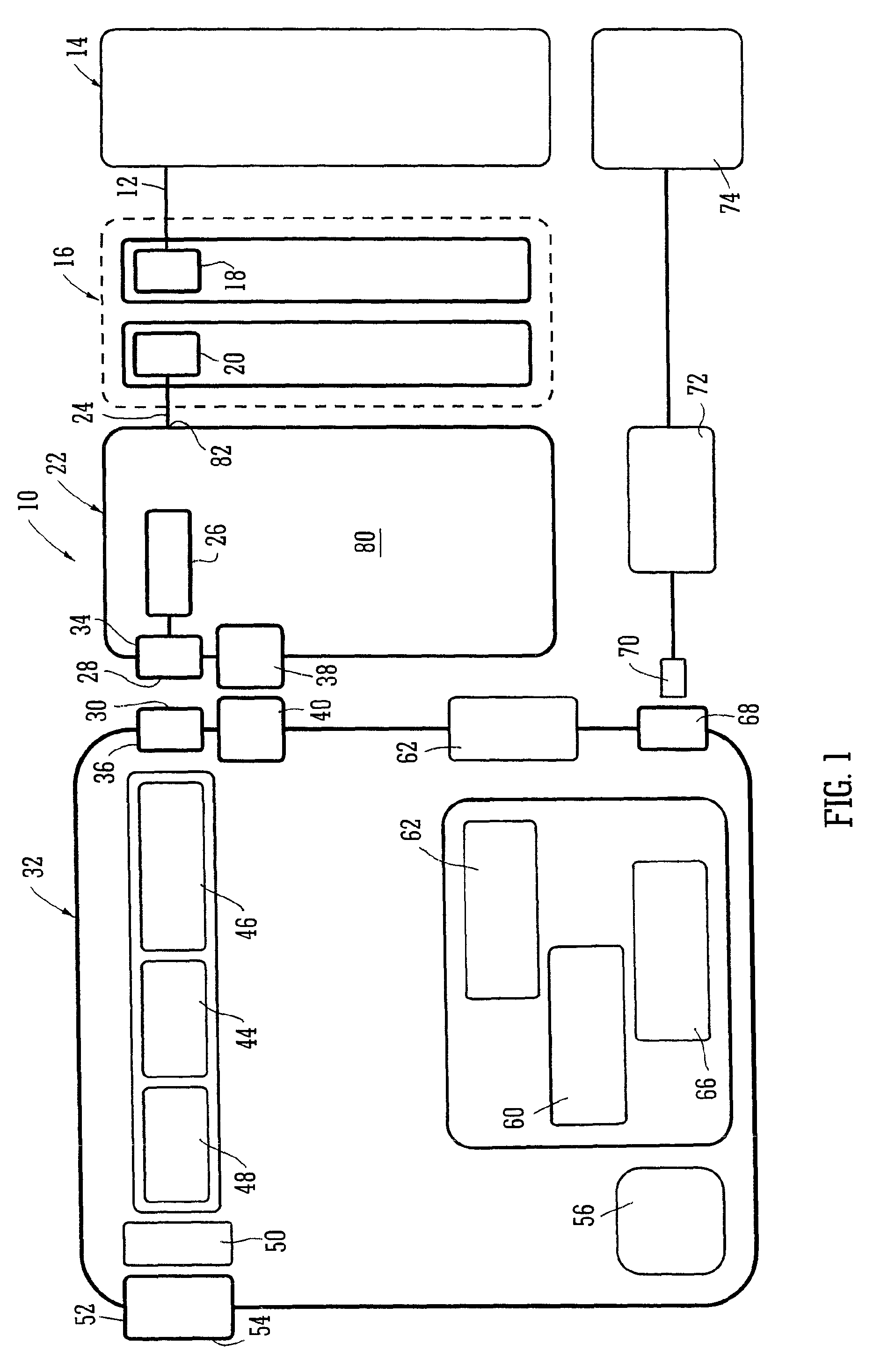
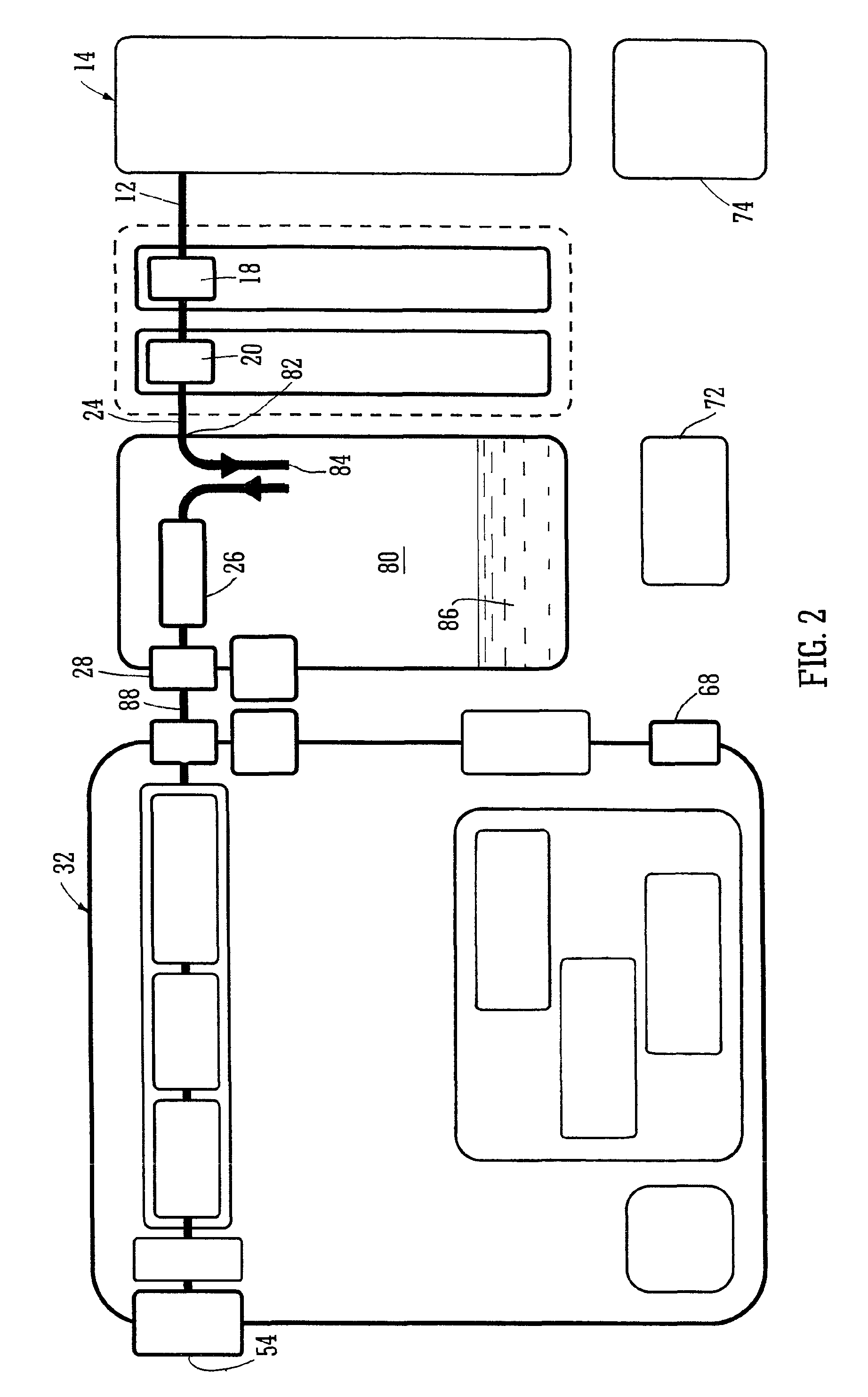
[0065]Referring now to FIGS. 1 to 4 of the drawings and where the same or similar features are denoted by common reference numerals.

[0066]FIG. 1 shows a generalised schematic view of an apparatus 10 of a portable topical negative pressure (TNP) system. It will be understood that embodiments of the present invention are generally applicable to use in such a TNP system. Briefly, negative pressure wound therapy assists in the closure and healing of many forms of “hard to heal” wounds by reducing tissue oedema; encouraging blood flow and granular tissue formation; removing excess exudate and may reduce bacterial load (and, therefore, infection). In addition the therapy allows for less disturbance of a wound leading to more rapid healing. The TNP system is detailed further hereinafter but in summary includes a portable body including a canister and a device with the device capable of providing an extended period of continuous therapy within at least a one year life span. The system is co...


PUM


Abstract

Apparatus (10, 200) for the provision of TNP therapy to a wound is described, the apparatus (10, 200) including: a waste canister (22, 204) into which fluid is aspirated from a wound by aspiration pump means (44, 248) and a fluid flow path (420, 422) for at least a part of said aspirated fluid on an outlet side of said aspiration pump means (44) wherein said fluid flow path (420, 422) on the outlet side comprises a silencing system (400) having a plurality of silencing elements (402, 404, 406) therein.

Description

BACKGROUND[0001]1. Technical Field[0002]The present invention relates to apparatus and a method for the application of topical negative pressure (TNP) therapy to wounds. In particular, but not exclusively, the present invention relates to minimising noise generated by TNP therapy apparatus.[0003]2. Description of the Related Art[0004]There is much prior art available relating to the provision of apparatus and methods of use thereof for the application of TNP therapy to wounds together with other therapeutic processes intended to enhance the effects of the TNP therapy. Examples of such prior art include those listed and briefly described below.[0005]TNP therapy assists in the closure and healing of wounds by reducing tissue oedema; encouraging blood flow and granulation of tissue; removing excess exudates and may reduce bacterial load and thus, infection to the wound. Furthermore, TNP therapy permits less outside disturbance of the wound and promotes more rapid healing.[0006]In our c...

Claims


Application Information

Patent Timeline
Patent Type & Authority Patents(United States)
IPC IPC(8): A61M27/00A61M1/00
CPCA61M1/0023A61M1/0027A61M1/0029A61M1/0031A61M1/0052A61M1/0066A61M1/0088A61M1/0096A61M27/00A61M2205/18A61M2205/3331A61M2205/3365A61M2205/3379A61M2205/42A61M2205/502A61M2205/75A61M2205/8206A61M2205/8262A61M1/732A61M1/734A61M1/74A61M1/784A61M1/80A61M1/882A61M1/79A61M1/82A61M1/982A61M1/96A61M1/60A61M1/88A61M1/984
Inventor MIDDLETON, MAXJACOB, STEPHEN
Owner SMITH & NEPHEW PLC
Why Eureka
Try Eureka