Gas turbine combustion chamber

a combustion chamber and gas turbine technology, applied in the combustion process, hot gas positive displacement engine plants, lighting and heating apparatus, etc., can solve the problems of high turbine inlet temperature, high flame temperature, and the need to increase the dwell time or the mixing length of the gas in the combustion chamber, so as to improve the intermixing effect, reduce the dwell time, and shorten the mixing length of the gas

Inactive Publication Date: 2015-11-24
SIEMENS AG
View PDF13 Cites 1 Cited by
  • Summary
  • Abstract
  • Description
  • Claims
  • Application Information

AI Technical Summary

Benefits of technology

[0009]Due to the turbulence generators, in particular on the inner side and / or the outer side of the pilot cone, improved intermixing between the pilot mixture developed in the pilot cone and the main mixture produced via the main burner, is obtained downstream of the pilot cone Improved combustion of the resulting pilot / main mixture is therefore produced downstream of the pilot cone. As a result, a reduction of the dwell time and a shortening of the mixing length of the gas in the combustion chamber is possible without increasing the CO values. Consequently, low NOx values are achieved even at high flame temperatures. As a result, measures for reducing NOx values can be dispensed with. Moreover, due to the reduction of cold, locally limited volumes in the combustion chamber, the stable operating range can be extended to a lower mean temperature with low CO emissions.

Problems solved by technology

High performance of such a gas turbine combustion chamber demands high turbine inlet temperatures which result from a high flame temperature.
However, for this it is necessary to increase the dwell time or the mixing length of the gas in the combustion chamber, for example by lengthening the combustion chamber.
However, this is in contradiction to a shortening of the dwell time for reduction of the NOx values.
This would, however, have a detrimental effect on the operation of the turbine under base load.
In addition, manufacturing costs would increase as a result.
Moreover, the availability of the machine could be restricted, which likewise would be a serious disadvantage.

Method used


Image

  • Gas turbine combustion chamber
  • Gas turbine combustion chamber
  • Gas turbine combustion chamber

Examples


Embodiment Construction

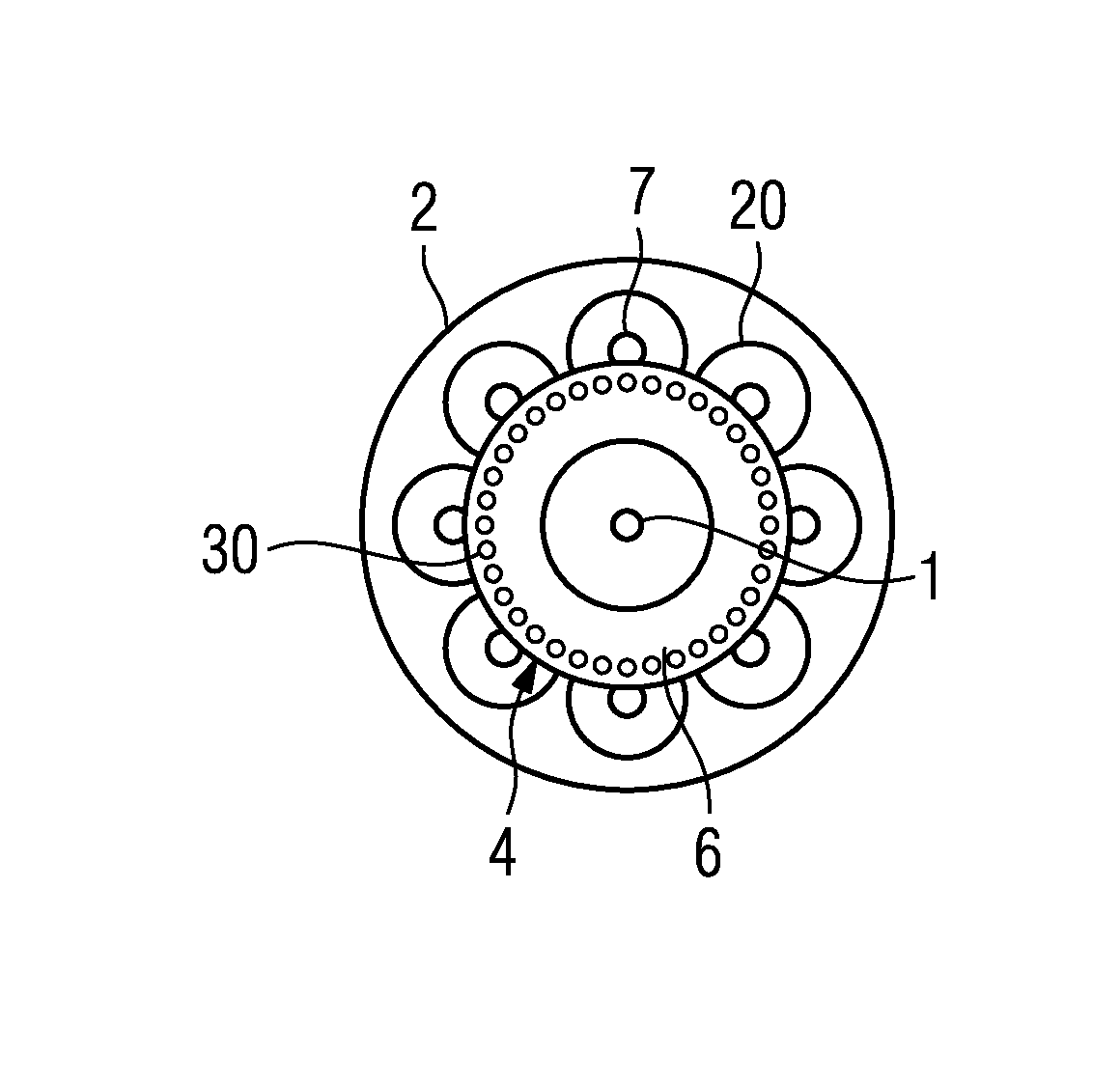
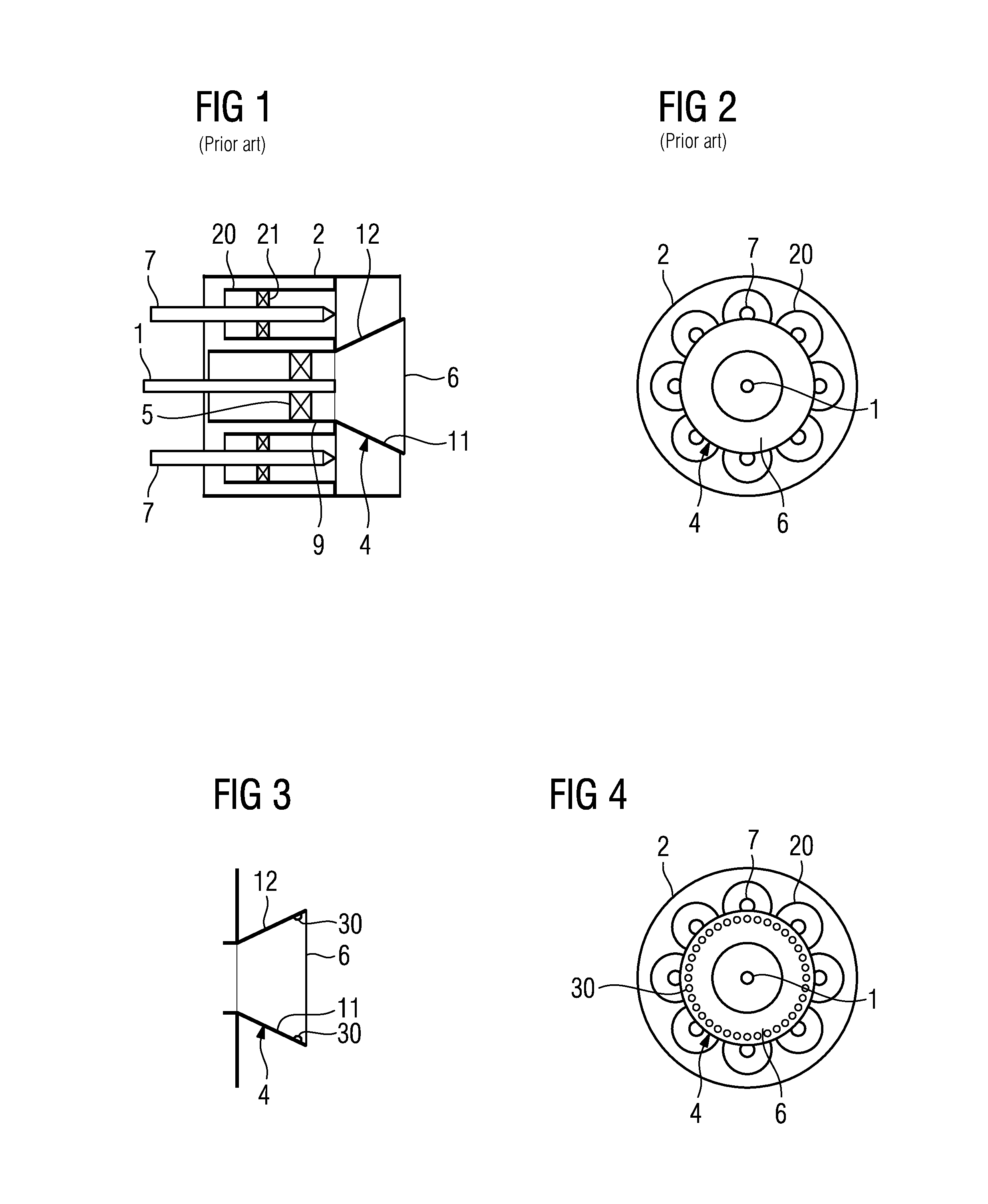
[0020]FIG. 1 and FIG. 2 show a gas turbine combustion chamber according to the prior art. Here the gas turbine combustion chamber has a pilot fuel nozzle which is arranged in the central section of a cylinder 2. The cylinder 2 opens at one end towards a combustion chamber (not shown). The pilot fuel nozzle contains a fuel nozzle 1 and a cylindrical outer casing 9 around the outer circumference of the fuel nozzle 1 and at a radial distance therefrom. A pilot swirl element 5 is arranged between fuel nozzle 1 and outer casing 9. A pilot cone 4 with inner side 11 and outer side 12 is arranged on the pilot fuel nozzle at the combustion chamber end. The pilot cone 4 has an opening 6 inside the front area of the cylinder 2. A plurality of main burners is arranged around the pilot fuel nozzle with respect to the radial direction. Each main burner has a main nozzle 7 and an outer cylinder 20 arranged with a gap around the outer circumference of the relevant main nozzle 7. In addition, main s...


PUM


Abstract

A gas turbine combustion chamber is provided including a pilot fuel nozzle arranged in the central section of a cylinder that opens at one end towards a combustion chamber. The pilot fuel nozzle includes a fuel nozzle and a cylindrical outer casing around the outer circumference of the fuel nozzle. A pilot swirl element is arranged between fuel nozzle and outer casing, including a plurality of main burners which are arranged around the pilot fuel nozzle, and including a pilot cone having an inner side and an outer side. The pilot cone is arranged on the pilot fuel nozzle and an opening, such that a pilot flame is formed in the pilot cone by mixing air and pilot fuel in order to ignite a fuel injected by the main burners, wherein the pilot cone has turbulence generators on the inner side and/or outer side thereof.

Description

CROSS REFERENCE TO RELATED APPLICATIONS[0001]This application is the US National Stage of International Application No. PCT / EP2011 / 059901, filed Jun. 15, 2011 and claims the benefit thereof. The International Application claims the benefits of European Patent Office application No. 10171601.7 EP filed Aug. 2, 2010. All of the applications are incorporated by reference herein in their entirety.FIELD OF INVENTION[0002]The present invention relates to a gas turbine combustion chamber as claimed in the claims.BACKGROUND OF INVENTION[0003]A gas turbine combustion chamber in which premixed combustion takes place is provided with a pilot burner for combustion in addition to the main burners for premixed combustion. The pilot burner serves to stabilize the combustion. The diffusion flame or premixed flame produced by the pilot is used as the pilot flame for the main burner in order to produce a more fuel-rich flame, which stabilizes the combustion. If necessary, a pilot burner can have a co...

Claims


Application Information

Patent Timeline
Patent Type & Authority Patents(United States)
IPC IPC(8): F02C1/00F23R3/34F23R3/28
CPCF23R3/28F23R3/343
Inventor PRADE, BERND
Owner SIEMENS AG
Why Eureka
Try Eureka