Conveyor, printing device, and box making machine

a printing device and conveying machine technology, applied in the direction of box making operations, paper/cardboard containers, printing press parts, etc., can solve the problems of paper dust generation, failure of sheet conveying, unclean factories, etc., to prevent paper dust generation, efficient exhaustion, and layout advantages

Active Publication Date: 2015-12-01
MITSUBISHI HEAVY IND MACHINERY SYST LTD
View PDF13 Cites 23 Cited by
  • Summary
  • Abstract
  • Description
  • Claims
  • Application Information

AI Technical Summary

Benefits of technology

[0012]To attain the above object, there is provided a conveyor that is disposed at a printing unit of a box making machine and conveys a corrugated sheet that is to undergo printing, including: a conveyor belt having a conveying face that conveys the corrugated sheet; a suction box that is disposed at a back side of the conveying face of the conveyor belt and that suctions the corrugated sheet onto the conveying face with negative pressure; a plurality of guide rolls that guide or drive the conveyor belt, the plurality of guide rolls including an inlet roll disposed at a side of an inlet where the corrugated sheet is fed onto the conveyor belt and an outlet roll disposed at a side of an outlet where the corrugated sheet is ejected from the conveyor belt; and air blowing means that is disposed on the back side of the conveyor belt within a region where the conveyor belt proceeds from the outlet roll to the inlet roll and that blows air to an outside.
[0030]The conveyor further includes a partition member that is disposed at the back side of the conveyor belt within the region where the conveyor belt proceeds from the outlet roll to the inlet roll, that extends along a cross direction of the conveyor, and that forms a compartment in combination with the back of the conveyor belt, so that the air blowing means blows the air inside the compartment and exhausts the air from the compartment. With this configuration, paper dust adhering to the back of the conveyor belt can be efficiently exhausted from the compartment.

Problems solved by technology

If the manufacture of such a paper product includes a step of cutting paper material, paper dust is generated by cutting the paper material.
Since such paper dust brings harm such as failure in printing, uncleanliness of factories, and failure in sheet conveyance due to stacked paper dust, techniques for removing paper dust has been developed.

Method used


Image

  • Conveyor, printing device, and box making machine
  • Conveyor, printing device, and box making machine
  • Conveyor, printing device, and box making machine

Examples


Embodiment Construction

[0051]Hereinafter, an embodiment of the present invention will now be described by referring to the accompanying drawings.

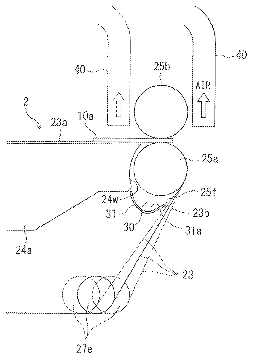
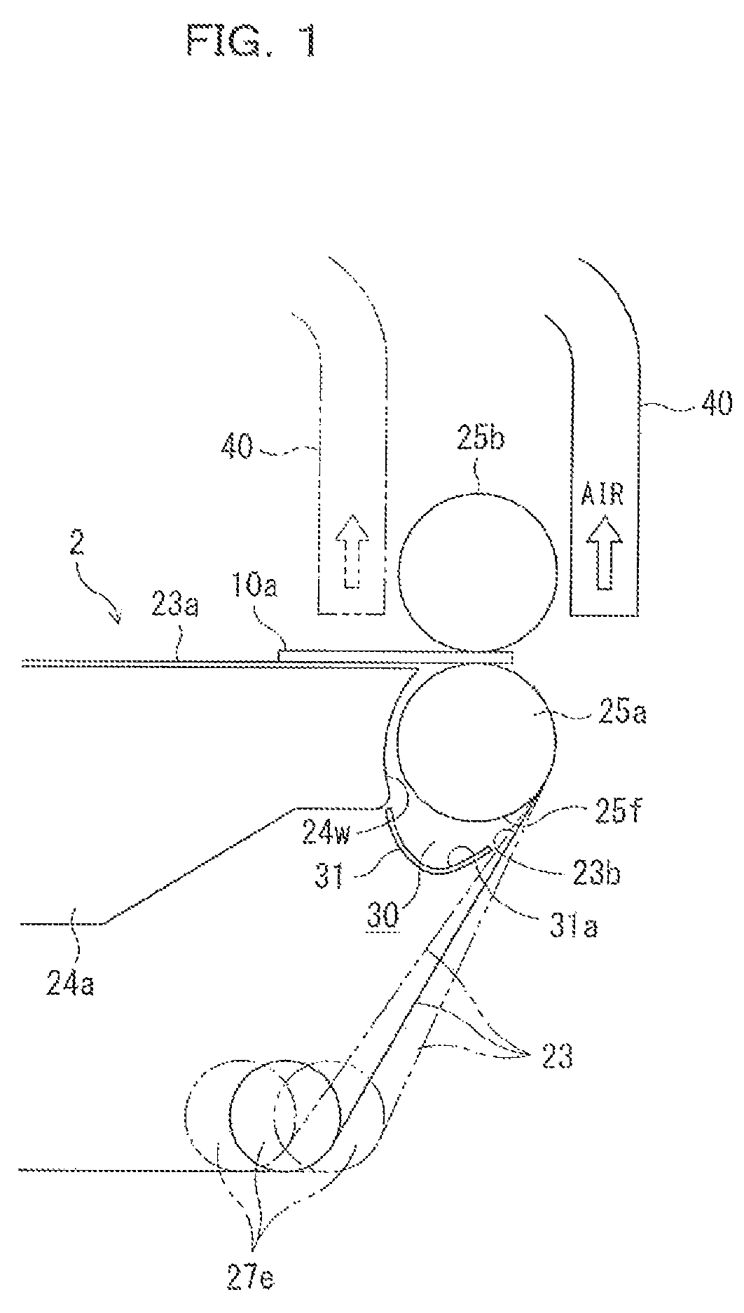
[0052]FIGS. 1-5 relates to the embodiment of the present invention. A conveyor, a printing device including the conveyor, and a box making machine including the printing device will now be described by referring to these drawings.

[0053]Box Making Machine:

[0054]First of all, a box making machine according to the embodiment will now be described by referring to FIG. 2.

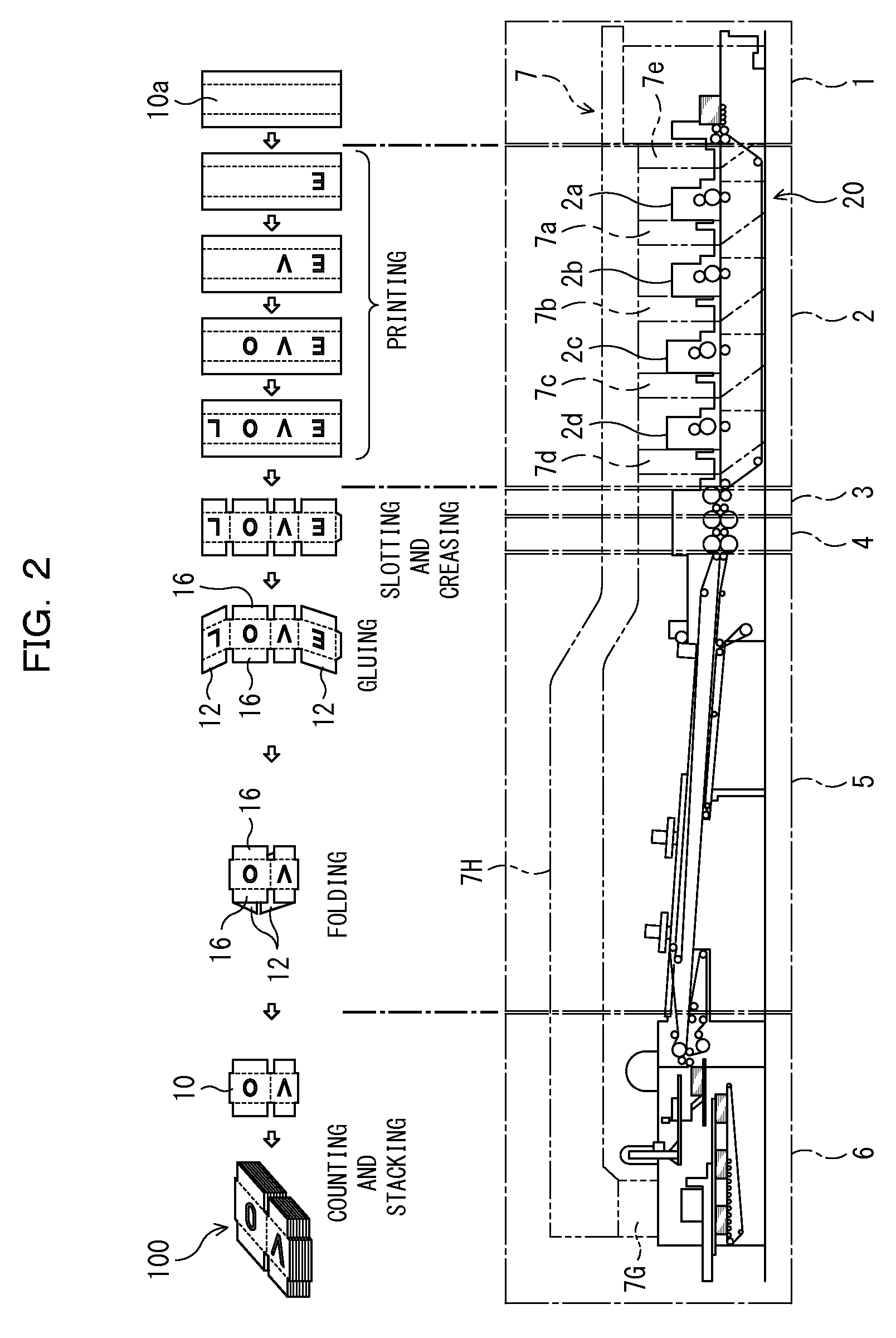
[0055]FIG. 2 illustrates a process of forming a corrugated sheet into a sheet ready to be formed into a box on the upper portion separately from the machine configuration illustrated at the lower portion. As illustrated in FIG. 2, the box making machine includes, sequentially from the upstream side, a feeding unit 1, a printing unit 2, a slotter creaser unit 3, a die cutting unit 4, a folder gluer unit 5, and a counter ejector unit 6.

[0056]Multiple corrugated sheets 10a are piled in the feeding unit 1...


PUM

PropertyMeasurementUnit
pressureaaaaaaaaaa
circumferenceaaaaaaaaaa
polarityaaaaaaaaaa

Abstract

A conveyor that is disposed at a printing unit of a box making machine and conveys a corrugated sheet 10a that is to undergo printing, includes: a conveyor belt 23 having a conveying face that conveys the corrugated sheet; a suction box 24a that is disposed at a side of a back 23b of the conveying face of the conveyor belt and that suctions the corrugated sheet onto the conveying face with negative pressure; a plurality of guide rolls that guide or drive the conveyor belt. Air blowing means is disposed on the back side of the conveyor belt within a region from an outlet roll to an inlet roll of the guide rolls and blows air to an outside.

Description

RELATED APPLICATIONS[0001]The present application is a National Phase of International Application Number PCT / JP2013 / 052546, filed Feb. 5, 2013, which claims priority to Japanese Application No. JP 2012-027089, filed Feb. 10, 2012.FIELD[0002]The present invention relates to a conveyor included in a printing unit of a box making machine, a printing device including the conveyor, and a box making machine including the printing device.BACKGROUND[0003]An example of a machine that manufactures paper products is a box making machine that manufactures a corrugated box from a corrugated sheet cut into a predetermined length in advance. An example of a box making machine includes, in sequence from the upstream side, a feeding unit, a printing unit, a slotter creaser unit, a die cutting unit, a folder gluer unit, and a counter ejector. The printing unit prints a letter and / or a picture on a corrugated sheet fed from the feeding unit, while conveying the corrugated sheet; the slotter creaser u...

Claims


Application Information

Patent Timeline
Patent Type & Authority Patents(United States)
IPC IPC(8): B65H39/02B65G15/58B41F3/00B65H5/22B31B1/88B31B50/88B31B70/04
CPCB65G15/58B31B1/88B65H5/224B41F3/00B65H2701/176B65H2406/35B65H2301/531B65H2801/21B41F35/007B41F5/02B41F21/00B41F22/00B31B50/88B65G45/22
Inventor NADACHI, MITSUHIROHATANO, OSAMU
Owner MITSUBISHI HEAVY IND MACHINERY SYST LTD
Why Eureka
Try Eureka