Jig for fixing laminated materials, a system for manufacturing bonded laminated materials, and a method for manufacturing bonded laminated materials

a technology of laminated materials and joints, which is applied in the direction of final product manufacturing, auxiliary welding devices, sustainable manufacturing/processing, etc., can solve the problems of inapplicability to continuous pressing devices, deformation of the bonding interface, and misalignment or deformation of the membrane, etc., to achieve easy measurement, simplify the structure of the machine, and the effect of wide width

Active Publication Date: 2013-11-21
SINTOKOGIO LTD
View PDF5 Cites 12 Cited by
  • Summary
  • Abstract
  • Description
  • Claims
  • Application Information

AI Technical Summary

Benefits of technology

[0173]With reference to FIG. 17, a variation of the exhausting portion 30b is described. In the configuration shown in FIG. 17(A), at the end portion of the exhausting portion 30b that is not connected to the housing portion 30a (a housing space), a portion 30c for smoothing the deformation is formed. The portion 30c for smoothing the deformation has a large width compared to the exhausting portion 30b. Its outer periphery is curved to be smoothly connected to the exhausting portion 30b, and has no corner. The exhaust hole 12a is disposed at the exhausting portion 30b. Since the portion 30c for smoothing the deformation is shaped as discussed above, the second sheet-shaped member 22 does not bend in a small area at the end portion of the exhausting portion 30b. Thus any wrinkle that can interrupt the exhaustion is avoided. The area of the portion 30c for smoothing the deformation is larger than that of the exhausting portion 30b. If the exhaust hole 12a is disposed at the portion 30c for smoothing the deformation, the second sheet-shaped member 22 may be sucked into it, so that then the hole 12a is occluded. Since the exhaust hole 12a is disposed along the exhaust passage of the exhausting portion 30b, any occlusion at the exhaust hole 12a is avoided. In this embodiment, the exhausting portion 30b extends from the end of the housing portion 30a to gently curve at a right angle. Thus since no large deformation of the second sheet-shaped member 22 in a small area at the connection of the housing portion 30a and the exhausting portion 30b or the bending of the exhausting portion 30b is generated, that configuration is more preferable. The exhausting portion 30b is not necessarily curved at a right angle. The portion 30c for smoothing the deformation may be provided at the end portion of the exhausting portion 30b that extends in a straight line from the end of the housing portion 30a.
[0174]In the configuration shown in FIG. 17(B), the exhausting portion 30b is formed as a loop, wherein both ends of it are connected to the housing portion 30a. The exhaust hole 12a is provided along the fluid path in the loop. In this embodiment, one end of the exhausting portion 30b is connected to the end portion of the housing portion 30a and another end is connected to another end portion of the housing portion 30a. The exhausting portion 30b gently curves as a loop, and has no corner. Since no portion of the second sheet-shaped member 22 is greatly deformed in a small area in the exhausting portion 30b, the exhausting from the housing space is not obstructed.
[0175]These configurations in FIG. 17 may be used for the jig for fixing laminated materials of the first and second embodiments.
[0176]With reference to FIG. 18, a cover for the flow path that prevents the exhausting portion from being occluded by the second sheet-shaped member is now described. The cover 70 for the flow path covers at least a portion of the exhausting portion 30b. It has a rectangular opening that is formed to expose the housing portion 30a. It is a rectangular plate. By using it, the second sheet-shaped member 22 is prevented from being sucked into the exhausting portion 30b when the housing space S is exhausted. Thus the exhaust hole 12a is prevented from being occluded by the second sheet-shaped member 22, and exhausting from the housing space S is not Obstructed. The cover 70 for the flow path may be integrated with the sealing member 30, for example, by adhering by means of a heat-resistant adhesive agent. In this configuration, since no gap is formed between the sealing member 30 and the cover 70 for the flow path, exhausting the housing space S is not obstructed by a leak. The shape of the cover 70 for the flow path is not limited to that in FIG. 18. In so far as it prevents the exhausting portion 30b from being obstructed by the second sheet-shaped member 22, the area of it to cover the exhausting portion 30b may vary. It may be constructed by blocks. The cover 70 for the flow path may be used for the jig for fixing the laminated materials of the first and second embodiments.
[0177]With reference to FIGS. 19 to 22, variations of the method for measuring a vacuum in the housing space are described. The machine 50 for manufacturing bonded laminated materials comprises a laser displacement meter 80 and a device 81 for fixing the laser displacement meter 80 to the machine for manufacturing bonded laminated materials. The laser displacement meter 80 is provided to measure a distance to at least a point of a portion J for measuring a displacement in the second sheet-shaped member 22 of the jig 1 for fixing laminated materials or the jig 2 for fixing laminated, materials when the jig 1 or the jig 2 is fed to the machine 50 for manufacturing bonded laminated materials or taken out from the machine 50. The portion J for measuring a displacement corresponds to a portion of the second sheet-shaped member 22, which portion is the housing space S that is to be made a vacuum, the exhausting portion 30b, or the flow space H, is formed. If the housing space S of the jig 1 for fixing laminated materials or the jig 2 for fixing laminated materials is decompressed, the distance of the portion J for measuring a displacement from the laser displacement meter 80 becomes longer, since the portion J for measuring a displacement is sucked toward the first sheet-shaped member 12. By measuring that distance, it can be checked if the housing space S has become a vacuum. Since the housing space S can be checked to see if it has become a vacuum when the jig 1 or the jig 2 is fed to the machine 50, transporting the jig 1 or the jig 2 starts after the housing space is checked to see if it has become a vacuum. Since the housing space S can be checked to see if it has become a vacuum when the jig 1 or the jig 2 is taken out from the machine 50, the jig 1 or the jig 2 can be thereafter taken out. By using the laser displacement meter 80, the degree of the vacuum is easily measured. Thus no piping to connect to the vacuum gauge 43 is needed unless a strict measurement of the degree of a vacuum is required. Thus the structure of the machine can be simplified.

Problems solved by technology

When the laminated materials of the polymer electrolyte, the fuel electrode, and the air electrode are pressed and bonded by a rolling-pressing device in the conventional technology, the membranes may be misaligned or deformed due to a rapid change in the load or friction between the rollers and the laminated materials that is generated when the materials pass between the rollers.
Further, if air remains between the membranes that are laminated, it is difficult to fully discharge the air, to thereby cause a deficiency in bonding at the interface.
However, since the above-mentioned frames for fixing a sheet that surround laminated materials are thicker than the materials, they are not applicable to a device for continuous pressing such as rolling-pressing or double-belt type pressing devices.
Thus the materials cannot be effectively manufactured.

Method used


Image

  • Jig for fixing laminated materials, a system for manufacturing bonded laminated materials, and a method for manufacturing bonded laminated materials
  • Jig for fixing laminated materials, a system for manufacturing bonded laminated materials, and a method for manufacturing bonded laminated materials
  • Jig for fixing laminated materials, a system for manufacturing bonded laminated materials, and a method for manufacturing bonded laminated materials

Examples


first embodiment

[0085]The jig for fixing laminated materials, the system for manufacturing bonded laminated materials, and the method for manufacturing bonded laminated materials of the present invention are, by taking the MEA as an example, now described with reference to the drawings.

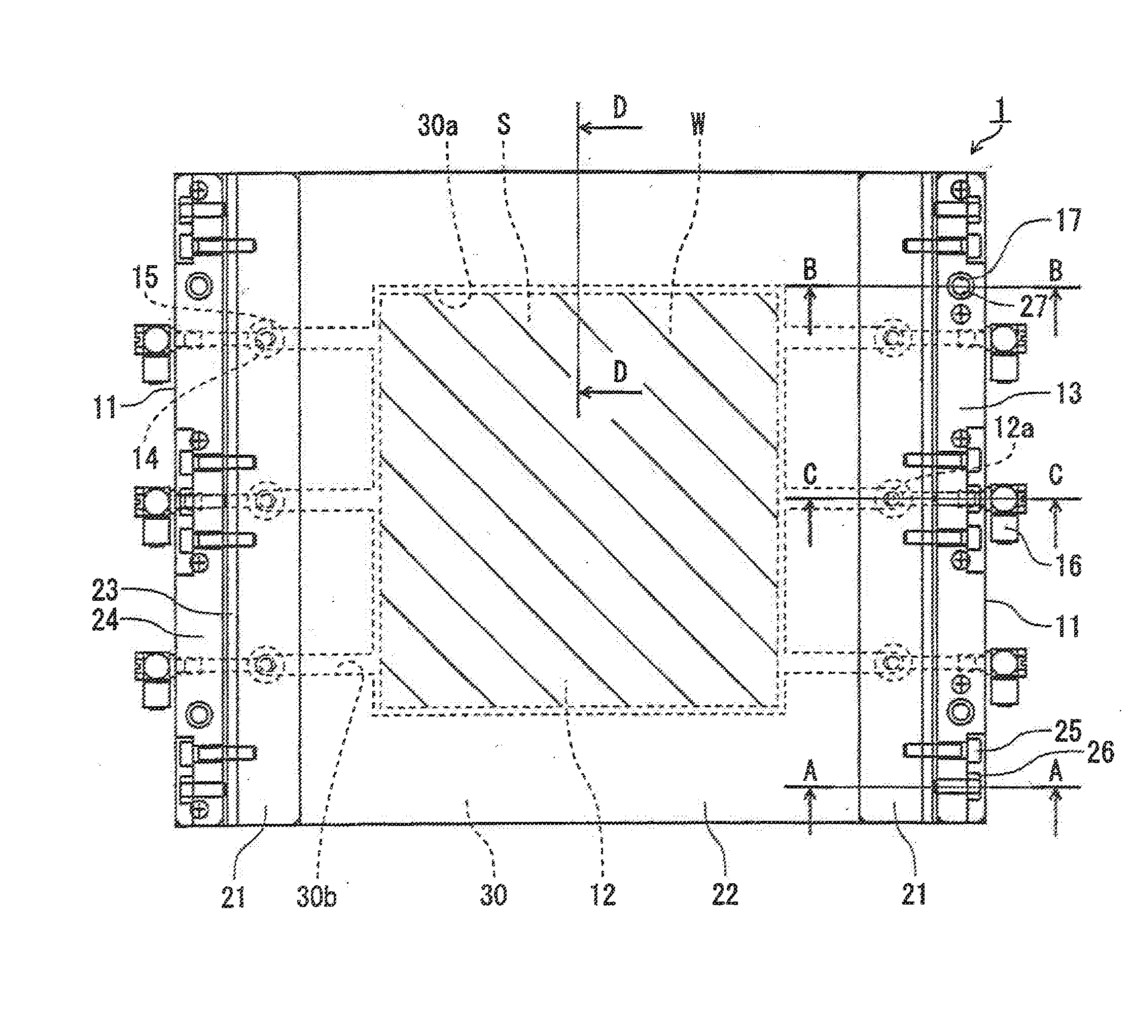
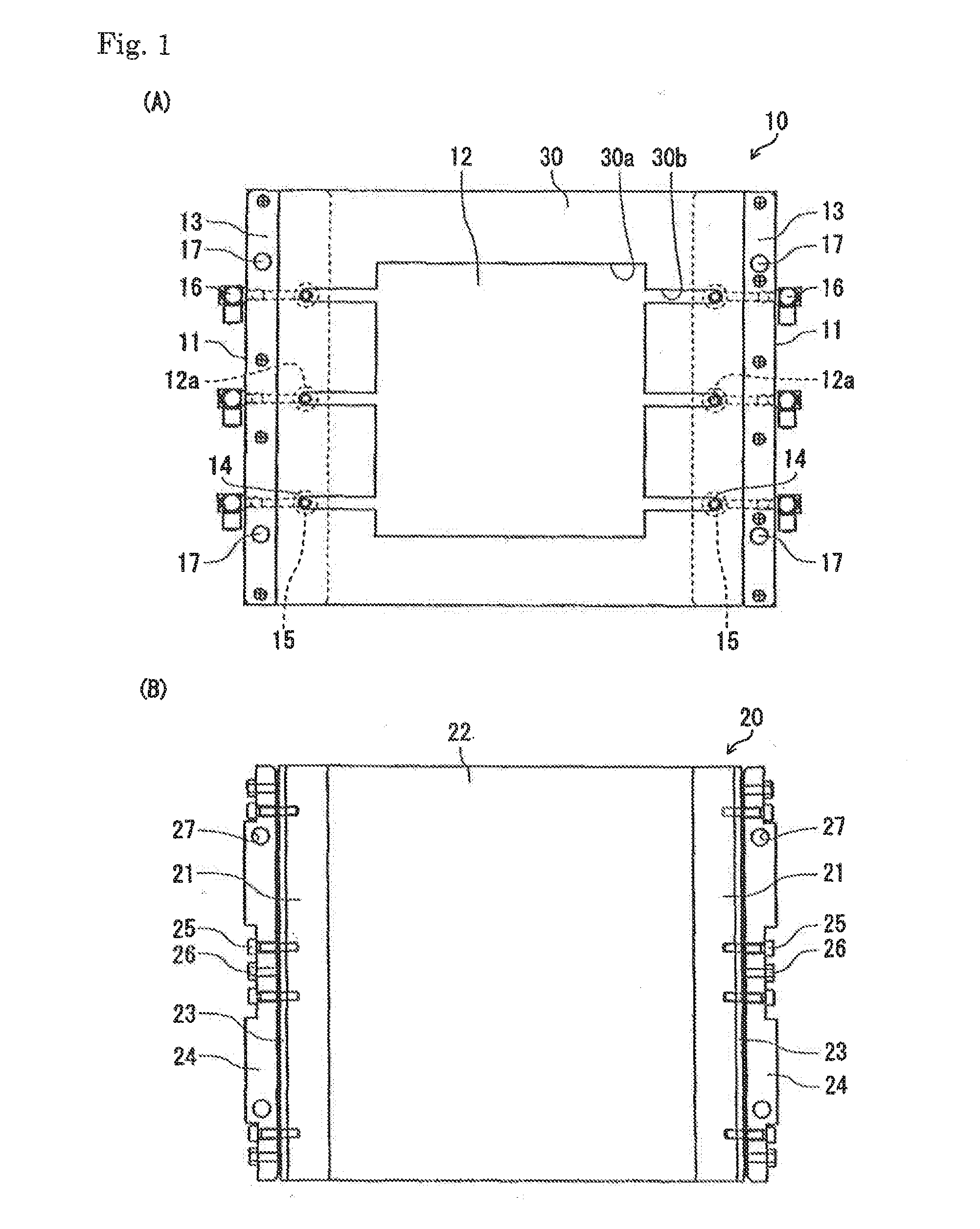
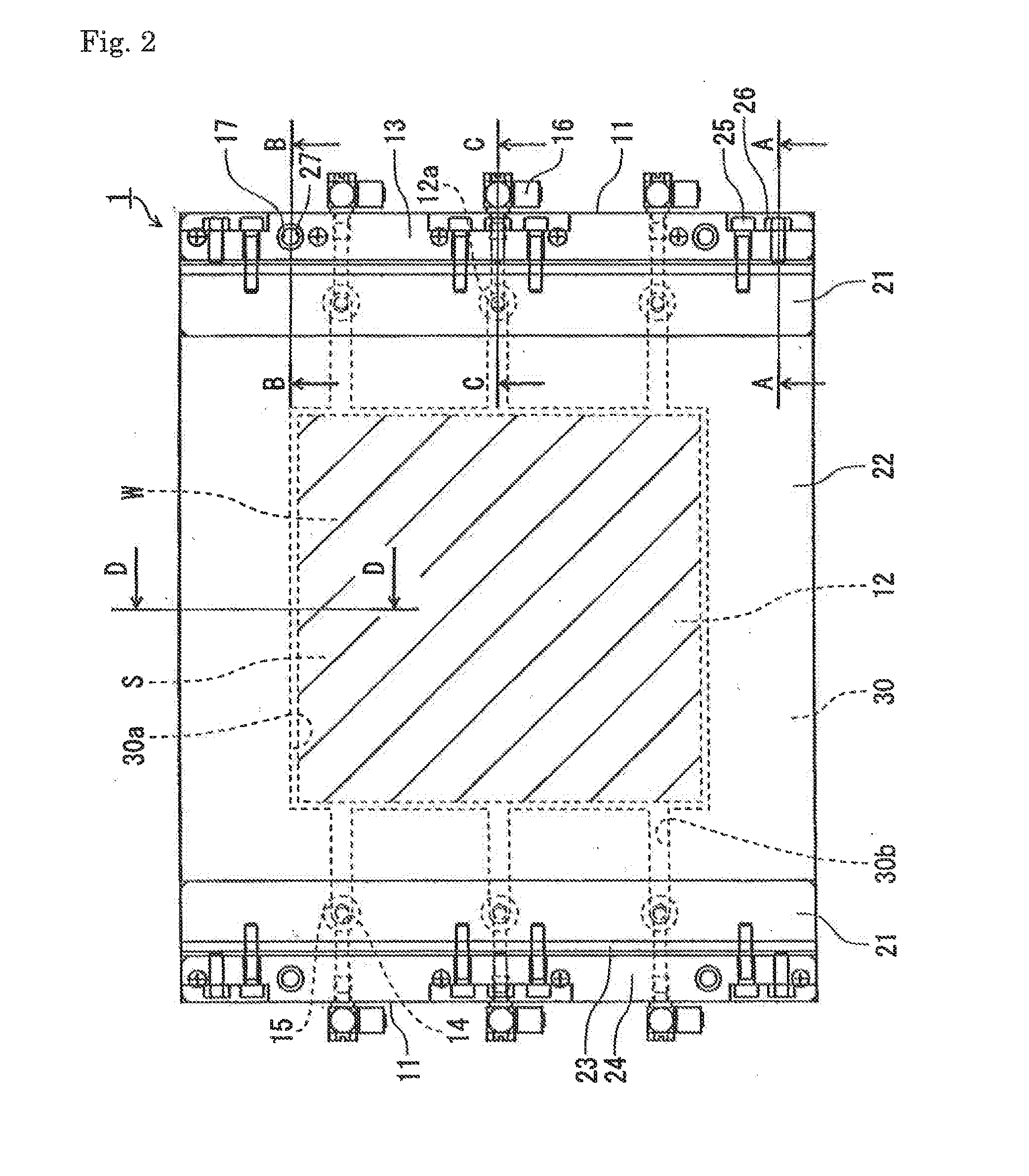
[0086]The structure of the jig 1 for fixing laminated materials is described with reference to FIGS. 1, 2, and 3. The jig 1 for fixing laminated materials comprises a first fixing member 10 that is connected to an exhaust device, a second fixing member 20 that is used in combination with the first fixing member 10, and a sealing member 30.

[0087]The first fixing member 10 is formed by spreading a first sheet-shaped member 12 between first columnar members 11, 11 that are disposed substantially parallel to the direction to be transported toward a machine 50 for manufacturing bonded laminated materials, which is described below. The first columnar members 11 are formed by rectangular columns. The first sheet-shaped memb...

second embodiment

[0150]With reference to the drawings, the second embodiment of the jig for fixing laminated materials of the present invention is discussed. The components that are the same as those in the first embodiment are denoted by the same numerals. So a duplicate description is omitted.

[0151]As shown in FIGS. 12, 13, and 14, the jig 2 for fixing the laminated materials of this embodiment has a member 31 for forming the housing space that is formed in the shape of a rectangular frame in the housing portion 30a of the first sheet-shaped member 12. In this embodiment, the member 31 for forming the housing space is made of stainless steel, which is a metal, at a thickness that is less than that of the laminated materials W. It is caused to adhere to the first sheet-shaped member 12 by a heat-resistant adhesive.

[0152]The member 31 for forming the housing space divides the housing portion 30a into the housing space S2 and the flow space H while it is sandwiched by the first sheet-shaped member 12...

working example

Working Example 1

[0178]In this example, an MEA for a solid polymer fuel cell is manufactured by using the jig for fixing laminated materials of the first embodiment and the machine for manufacturing bonded laminated materials, as in FIG. 6. The present invention is not limited to the following working examples.

[0179]The polymer electrolyte that constitutes the MEA is a square sheet 200 mm long and 200 mm wide that is cut from a sheet 50 μm thick. The fuel electrode and the air electrode are square sheets 190 mm long and 190 mm wide that are cut from a sheet 400 μm thick. The polymer electrolyte is a sheet made of Nafion (a registered trademark), supplied by DuPont. The fuel electrode and the air electrode are sheets made by having carbon paper support platinum catalysts.

[0180]A stainless steel sheet 300 μm thick that is polished to a mirror finish on both sides is used for the first sheet-shaped member. A sheet made of Teflon (a registered trademark) 300 μm thick is used for the sec...


PUM

PropertyMeasurementUnit
temperatureaaaaaaaaaa

Abstract

A jig for fixing laminated materials, a system for manufacturing bonded laminated materials, and a method of manufacturing bonded laminated materials are provided at a good yield factor and to efficiently manufacture the bonded laminated materials that are pressed and bonded after being laminated without a misalignment of the membranes or deformation of the laminated materials or any deficiency in bonding at the interface. The bonded laminated materials are manufactured by storing materials made of laminated membranes (W) in a housing space (S) formed by a first sheet-shaped member (12), a second sheet-shaped member (22), and a sealing member (30), exhausting the housing space (S) to sandwich the laminated membranes (W) between the first and second sheet-shaped members (12, 22) to fix them, and pressing and bonding them by hot-pressing rollers (51) and cold-pressing rollers (52) of a machine (50) for manufacturing the bonded laminated materials while they are fixed.

Description

TECHNICAL FIELD[0001]The present invention relates to a jig for fixing laminated materials that is used for manufacturing bonded laminated materials, such as a membrane-electrode assembly for a solid polymer fuel cell, by pressing and bonding laminated materials. It also relates to a system for manufacturing bonded laminated materials and a method for manufacturing bonded laminated materials.BACKGROUND ART[0002]Conventionally, a rolling-pressing device has been used to manufacture bonded laminated materials by pressing and bonding materials having laminated membranes. It presses the laminated materials between rollers that face one another while the materials are transported between them. This technology has recently been used for manufacturing a membrane-electrode assembly (MEA) for a solid polymer fuel cell, which is manufactured by laminating a polymer electrolyte, a fuel electrode, and an air electrode, and bonding them. (See, for example, Japanese Patent Laid-open publication N...

Claims


Application Information

Patent Timeline
Patent Type & Authority Applications(United States)
IPC IPC(8): B32B37/00
CPCB32B37/0046B30B3/04B30B15/34B32B37/003B32B37/10B32B38/1833B32B2309/68B32B2457/18H01M8/0271H01M8/1004Y02E60/50Y02P70/50B30B3/00B30B15/00H01M8/02H01M8/10
Inventor NAGASAKA, MASAHIKONAKAJIMA, SHOGONOZAWA, TAKAYUKISUGINO, OSAMUMISHIMA, IKUTO
Owner SINTOKOGIO LTD
Why Eureka
Try Eureka