Uninterrupted alternating air circulation for continuous drying lumber kilns

a technology of alternating air circulation and continuous drying, which is applied in the direction of drying machines with progressive movements, lighting and heating apparatus, furnaces, etc. it can solve the problems of increased fire risk, inability to fully resume heat production, and the dynamics of direct fired burners may require time to return to full operating levels of heat production. , to achieve the effect of improving the quality and uniformity of lumber being processed, reducing the time and energy required to heat lumber, and enhancing the safety of kiln

Active Publication Date: 2015-12-01
KILN DRYING SYST & COMPONENTS LLC
View PDF19 Cites 36 Cited by
  • Summary
  • Abstract
  • Description
  • Claims
  • Application Information

AI Technical Summary

Benefits of technology

[0026]The present disclosure teaches the use of dual track continuous drying kilns (CDK) that do not periodically reverse fan direction. Elimination of fan reversals will enhance kiln fire safety and reduce the time and energy required to heat lumber in kilns, while improving the quality and uniformity of lumber being processed. Aspects of the teachings contained within this disclosure are addressed in the claims submitted with this application upon filing. Rather than adding redundant restatements of the contents of the claims, these claims should be considered incorporated by reference into this summary.

Problems solved by technology

However, even a momentary lack of circulation in an energy recover section can increase fire risk as the circulation of cooler moist air from the green lumber 140 abates and a hot spot may progress to an open fire.
While the time to allow the fans to coast to a stop and restart may be as short as five minutes, some interruptions in the provision of heat may be in the 15 minute range as the heating system may be turned off before the fans are de-energized and heat may not be fully resumed for a few minutes after the fans have been re-energized.
After idling, the dynamics of the direct fired burner may require time to return to full operating levels of heat production.
4) Heated and now dry lumber does not receive the circulation from green lumber and may develop overheated sections.

Method used


Image

  • Uninterrupted alternating air circulation for continuous drying lumber kilns
  • Uninterrupted alternating air circulation for continuous drying lumber kilns
  • Uninterrupted alternating air circulation for continuous drying lumber kilns

Examples


Embodiment Construction

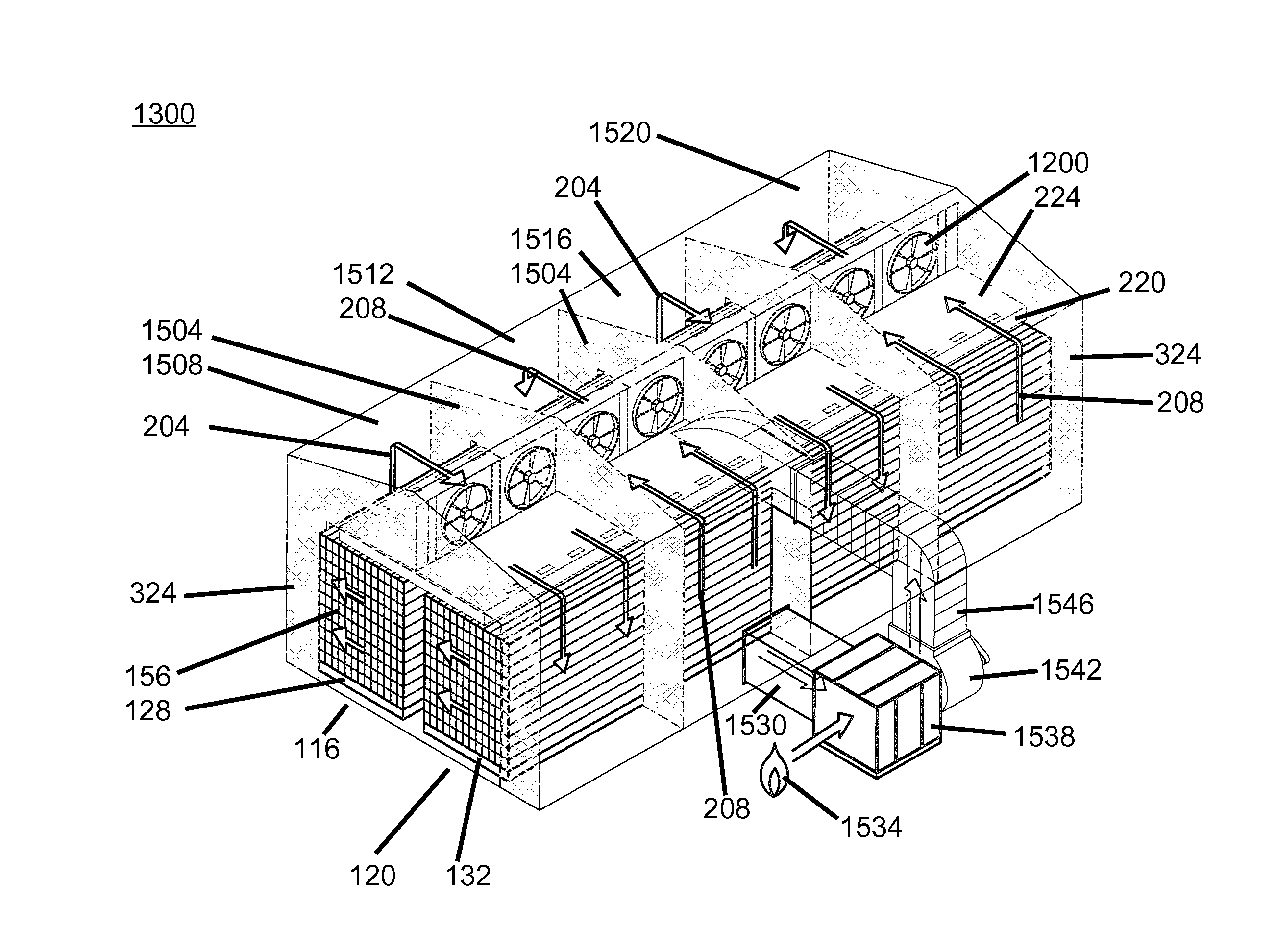
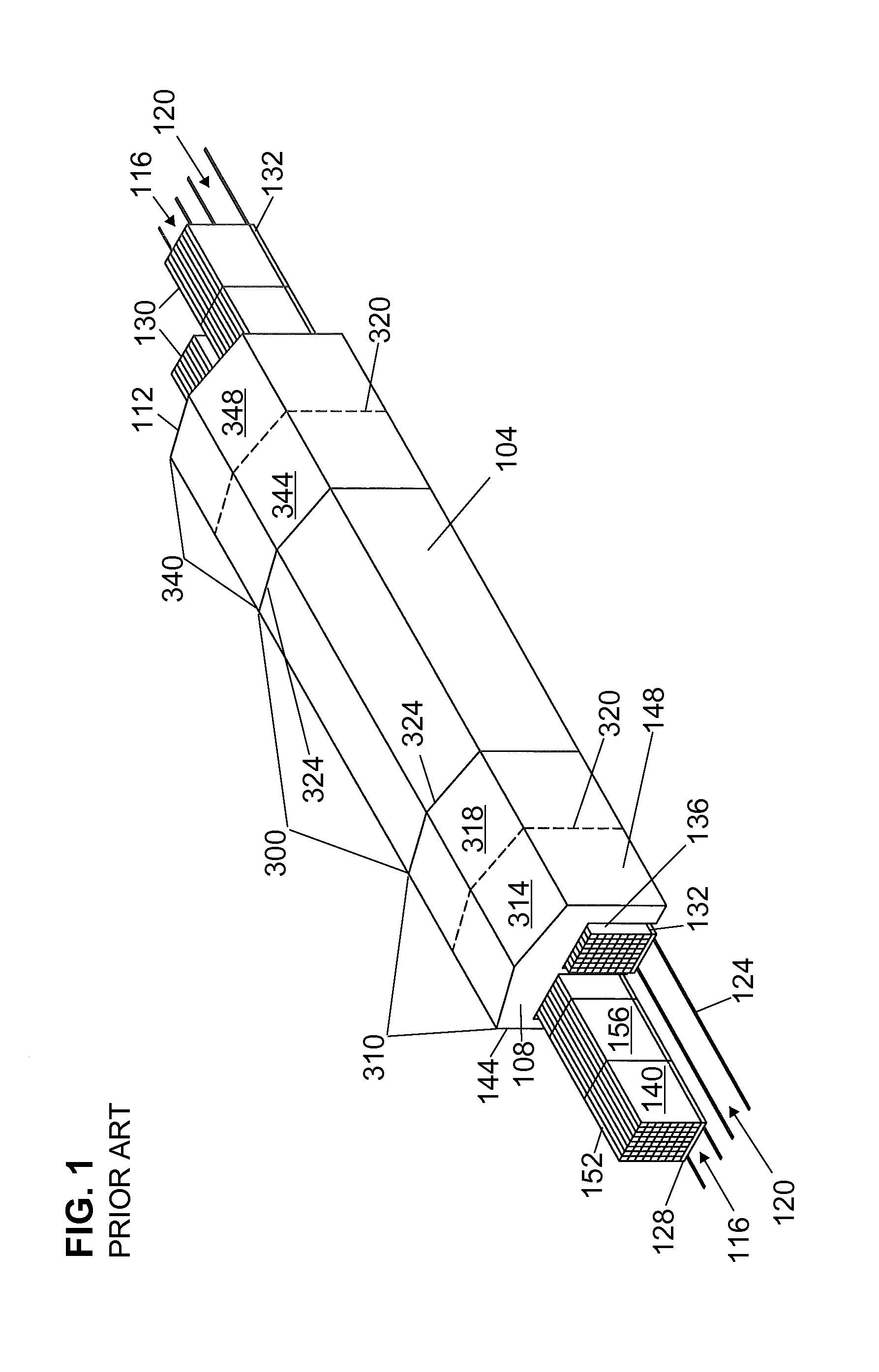
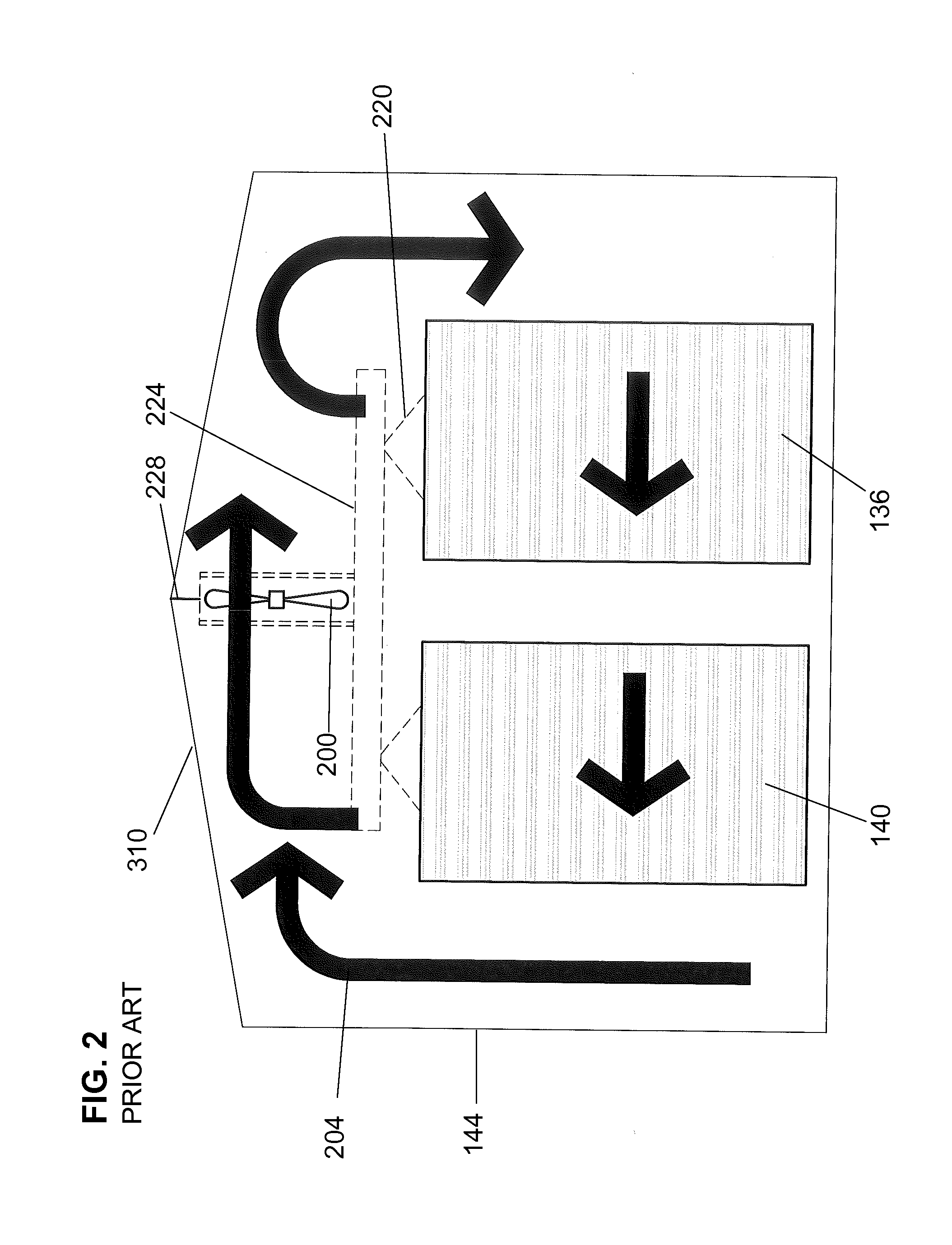
[0037]FIG. 4 shows a structure 1104 that illustrates some of the teachings of the present disclosure. Many elements present in FIG. 4 were introduced during the discussion of prior art structure 104 in FIG. 1. Structure 1104 has a first end 108 and a second end 112 and a first side 144 and a second side 148. Lumber 130 is stacked upon the first set of carriages 128 on rails 124 forming the first pathway 116 to traverse the structure 1104 from the first end 108 through the second end 112. Lumber 130 is stacked upon the second set of carriages 132 to traverse the structure 1104 from the second end 112 through the first end 108. The manner of stacking lumber 130 upon carriages with spacers (sometimes called “stickers”) and weights may be the same as discussed in connection with FIG. 1. As described in more detail below, the lumber 130 is exposed to periods of air movement in the first circulation direction 204 and to periods of air movement in the second circulation direction 208 as th...


PUM


Abstract

A continuous drying kiln (CDK) design, in which two sets of carriages carrying spaced stacks of lumber travel in opposite directions through a sequence of chambers in which green lumber is exposed to heated air to dry the lumber to desired conditions. The continuous drying kiln using fans in each chamber to circulate air across the stacked lumber on the two sets of carriages, orthogonal to the direction of carriage travel, in either a first circulation direction or in a second circulation direction. As a carriage moves from chamber to chamber, the circulation direction is reversed.

Description

BACKGROUNDField of the Disclosure[0001]This disclosure applies only to systems of the continuous drying kiln (CDK) design, (also referred to as dual path or triple length kilns), in which two paths of lumber travel in opposite directions through a sequence of chambers in which wood is pre-heated, dried, equalized and then conditioned.[0002]FIG. 1 introduces a series of elements found in continuous drying kilns. Typically a continuous drying kiln will have a structure 104 with a first end 108 and a second end 112 at the opposite end of the structure 104. Running through the structure 104, is a first pathway 116 and a second pathway 120. The pathways frequently use rails 124 to guide a first set of carriages 128 along the first pathway 116 and a second set of carriages 132 along the second pathway 120. The carriages (128132) may have wheels (not shown) much like those found on railroad cars.[0003]If the first set of carriages 128 enters the structure 104 through the first end 108 and ...

Claims


Application Information

Patent Timeline
Patent Type & Authority Patents(United States)
IPC IPC(8): F26B3/04F26B15/16F26B23/02F26B3/02
CPCF26B3/02F26B25/063F26B15/16F26B23/02F26B21/002F26B25/008F26B3/04F26B2210/16F26B3/06F26B21/004F26B21/022F26B21/028
Inventor BALL, JR., TROY EUGENEGIRARDI, ROBERTPOLLOCK, ROBERT KING
Owner KILN DRYING SYST & COMPONENTS LLC
Why Eureka
Try Eureka