
Multiple simultaneous transmit track beams using phase-only pattern synthesis

a track beam and phase-only technology, applied in the field of radar tracking, can solve the problems of reducing sensitivity, limiting the number of other operations that can be scheduled, and large amount of wasted energy being sent to the angles where targets are located, so as to achieve the effect of increasing the dwell tim

Active Publication Date: 2015-12-01
LOCKHEED MARTIN CORP
View PDF14 Cites 8 Cited by
  • Summary
  • Abstract
  • Description
  • Claims
  • Application Information

AI Technical Summary

Benefits of technology

The patent describes a method for a radar system to track multiple objects simultaneously. It involves using a side lobe radar transmit signal to accurately align with a secondary target and increasing the dwell time for the main lobe transmit signal. The method also allows the radar system to designate the secondary target as the primary target if its return signal strength is weaker than that of other targets. This designation enables the radar system to track the weaker target with the side lobe transmit signal. Overall, this method improves the radar system's ability to track multiple objects simultaneously.

Problems solved by technology

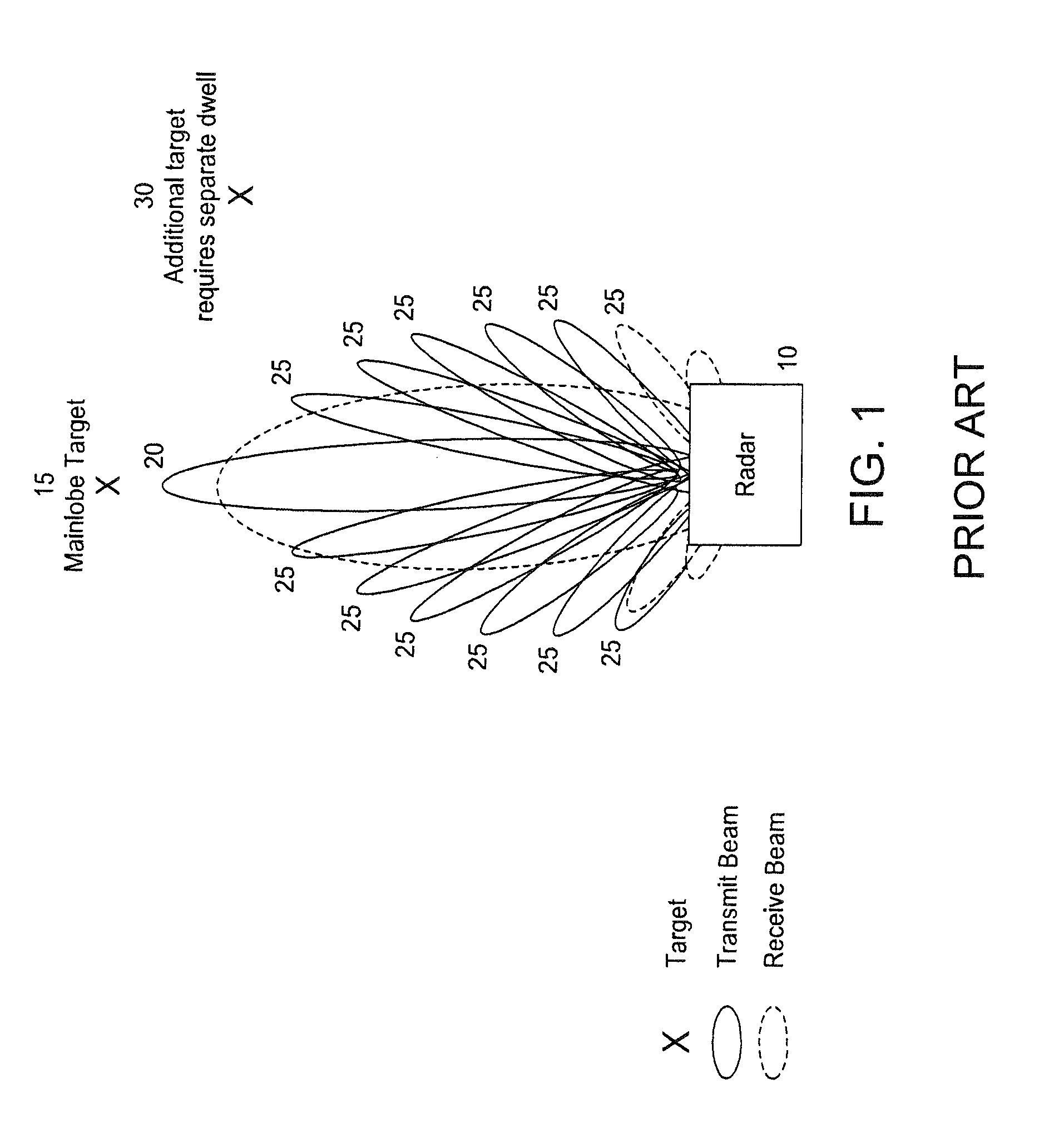
Method one results in high track resource utilization, which limits the number of other operations (such as search) that can be scheduled for a radar.
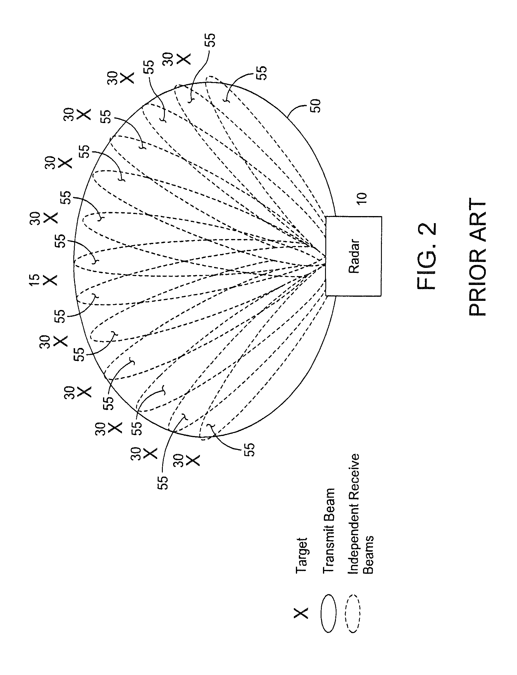
Method 2 can be effective for searching a large volume, but beamspoiling the transmit beam results in a large amount of wasted energy being sent to angles where targets are not present.
Method three uses lower power and lower gain, resulting in decreased sensitivity and decreased angular resolution.
Finally, while the shotgunning method is sometimes effective, on its own it may not be effective if the radar is not able to quickly switch from transmitting one pulse to the next.
The use of a new main lobe for each target consumes significant radar resources, and each new main lobe has associated wasted sidelobe energy that is not utilized.
The wide transmit beam pattern can detect a primary target 15 as well as secondary targets 30, but significant radar resources are wasted because the wide transmit beam sends energy in all directions regardless of where the targets are.
In addition, as is known in the art, beamspoiling results in a loss of gain, therefore longer dwell times are needed using this prior art method.

Method used


Image

  • Multiple simultaneous transmit track beams using phase-only pattern synthesis
  • Multiple simultaneous transmit track beams using phase-only pattern synthesis
  • Multiple simultaneous transmit track beams using phase-only pattern synthesis

Examples


Embodiment Construction

[0025]This invention provides a method for tracking multiple targets while minimizing radar resources and increasing Doppler sensitivity.

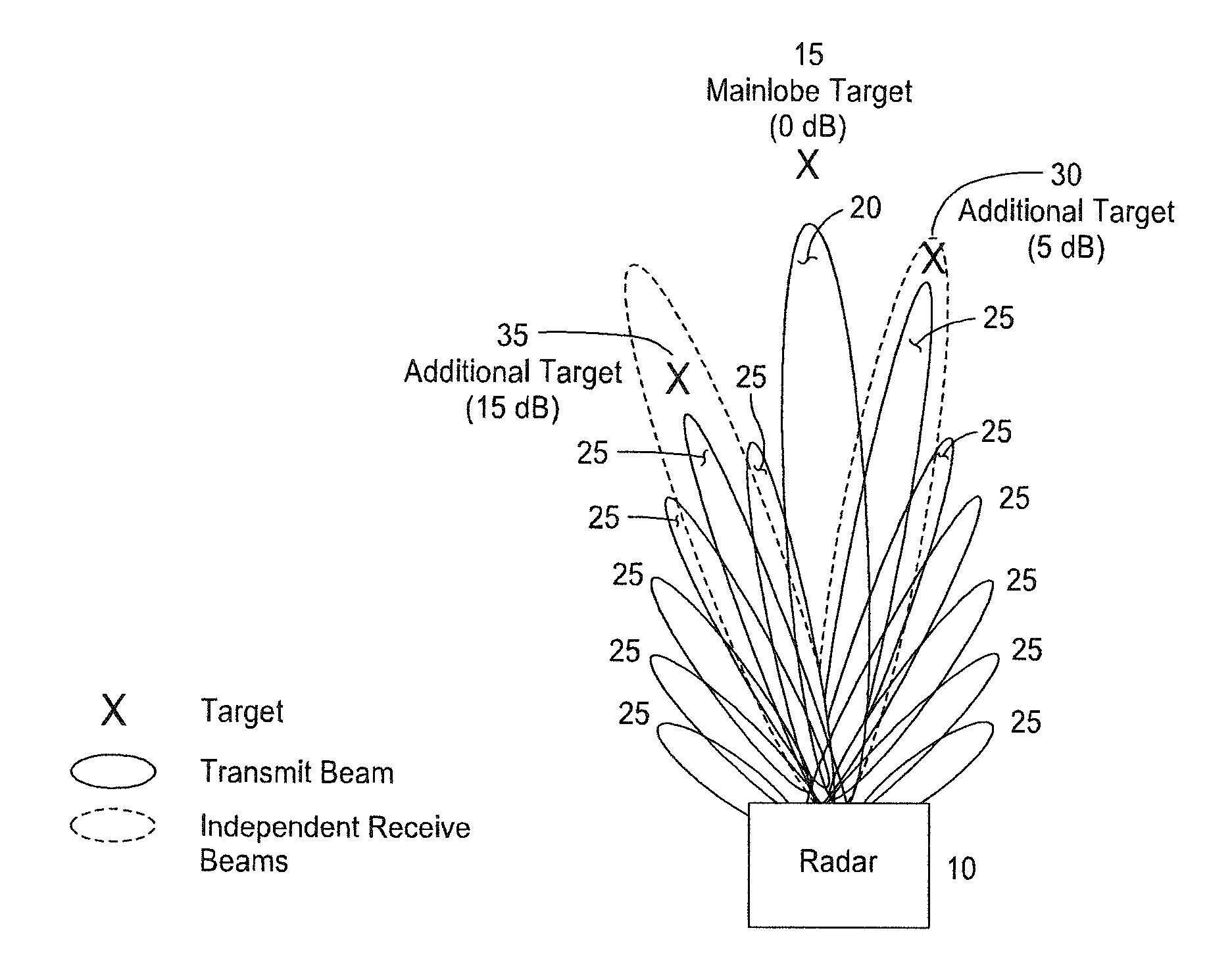
[0026]FIG. 3 shows a notional representation of a method for tracking multiple targets according to an embodiment of the disclosure. Radar 10 is configured to emit a standard radar transmit signal with a main lobe 20 directed at the primary target 15 and associated sidelobes 25. If a secondary target 30 is identified as being within a sidelobe 25 and has a strong return signal (e.g., because it has a large radar cross section or because it is close to the radar), an independent digital receive beam 35 may be formed in the direction of the secondary target, to substantially align with the secondary target. In this way, a primary target and a secondary target may be tracked in the same time that a single primary target would be tracked. Thus, this method avoids tracking using the prior art method of tracking each target with a separate main lobe. Thi...


PUM


Abstract

A radar tracking method and system is disclosed that improves radar resource utilization and increases Doppler resolution. The method includes tracking a primary target and a secondary target by directing a radar transmit signal main lobe at a primary target, the radar transmit signal main lobe having associated radar transmit signal side lobes, and receiving a main lobe radar return signal and side lobe radar return signals. A secondary target proximate to a first side lobe radar transmit signal is identified. Then, the primary target is tracked using the radar transmit signal main lobe and the main lobe radar return signal, and the secondary target is tracked using the first side lobe radar transmit signal proximate the secondary target and an independent side lobe return beam formed to align with the secondary target.

Description

FIELD OF THE INVENTION[0001]The present invention relates to radar tracking, and more particularly to a method and system for tracking multiple targets with multiple simultaneous track beams using phase-only pattern synthesis.BACKGROUND OF THE INVENTION[0002]Radar resource utilization is a high priority in military radars. Radar is used to scan for new threats as well as to keep track of already identified threats. Conserving radar resource utilization in one application can free up the radar for other applications.[0003]Simultaneous tracking of multiple targets has been implemented in primarily four ways in the past: 1) tracking one target for a single pulse or dwell and then quickly switching to one or more additional targets; 2) beamspoiling on transmit and forming multiple receive beams; 3) partitioning the array faces into different subapertures and then forming a different transmit beam out of each subaperture; and 4) shotgunning, which is transmitting different pulses to mult...

Claims


Application Information

Patent Timeline
IPC IPC(8): G01S13/72G01S7/41G01S13/00
CPCG01S13/726G01S7/41G01S13/72G01S7/282G01S13/42G01S2013/0245
Inventor MANICKAM, ARULKAUP, PETER G.LOBERGER, DAVID G.
Owner LOCKHEED MARTIN CORP
Learn More