Cloth material

a cloth material and cloth material technology, applied in the field of cloth material, can solve the problems of reducing affecting the quality of the external appearance, and affecting the ability of the cloth material to follow the shape of the seat, so as to reduce the connection pressure, the flexibility of the cloth material itself can be sufficiently maintained, and the effect of reducing the pressur

Active Publication Date: 2015-12-01
TOYOTA BOSHOKU KK
View PDF11 Cites 0 Cited by
  • Summary
  • Abstract
  • Description
  • Claims
  • Application Information

AI Technical Summary

Benefits of technology

[0009]With the cloth material described above, the connecting member for providing electrical interconnection is welded sandwiching the end portions of the conductive wires (i.e., the exposed portions) and the side portion of the cloth material main body having the conductive wires. Also, the welded portions formed by this welding are arranged lined up at intervals in a line with the non-welded portions in between. Therefore, a loss of flexibility of the cloth material end portion due to attaching the connecting member onto the surface can be inhibited, so flexibility of the cloth material itself can be sufficiently maintained. Moreover, a decrease in the connection pressure due to thread breakage that may occur with sewing will not occur, so the connection pressure is able to be maintained over an extended period of time. Also, when the welded portions are formed on the conductive wires, the conductive wires are able to be more reliably electrically connected together. Furthermore, the outer periphery of the welded portions is formed round, so damage to the conductive wires during welding is able to be sufficiently inhibited. Also, the welded portions are concave portions that are recessed with respect to the surrounding area, and are formed so as to change in a rounded manner without any corners, from the bottom surface portion to the side surface portion of the concave portions, so damage to the conductive wires during welding is able to be sufficiently inhibited. Also, by forming the plurality of rows parallel, the connection area needed for electrical connection is able to be sufficiently obtained, and the connection pressure is able to be maintained over an extended period of time. Moreover, the welded portions that are adjacent in a given row, from among the plurality of rows, are arranged such that, if another row were parallel-shifted so as to overlap with the given row, at least a portion of the welded portions in the given row would overlap with the welded portions in the other row, and the alternately arranged welded portions would be connected by the welded portions that are adjacent in the given row overlapping with the plurality of welded portions that have been parallel-shifted. Therefore, the exposed portions of the conductive wires are able to be reliably sandwiched by the welded portions, such that the plurality of conductive wires are able to be reliably electrically connected together.

Problems solved by technology

Also, a bonded portion of the end portion of the material cloth ends up hardening by this kind of complete face-bonding, so flexibility of the cloth material itself ends up being lost.
If the cloth material has poor flexibility, the ability of the cloth material to follow the shape of the seat is diminished and the quality of the external appearance may be lost.
Also, when a person is seated, the cloth material may feel hard and be uncomfortable to the seated person.
However, if a thread breaks in one seam, the connection pressure ends up decreasing over the entire seam, so an electrical connection with the conductive wire may no longer be able to be sufficiently obtained.
Furthermore, with sewing, the connection area of the planar bodies on the front and back is small, and in order to obtain the necessary connection area, sewing must be performed at least twice, which leads to an increase in the number of processes.
Also, the conductive wire or conducting wire that gives the planar body conductivity may end up breaking due to contact between a sewing needle and the conductive wire or the conducting wire when sewing is being performed.
Moreover, the sewing needle may tend to wear from this contact.

Method used


Image

  • Cloth material
  • Cloth material
  • Cloth material

Examples


Embodiment Construction

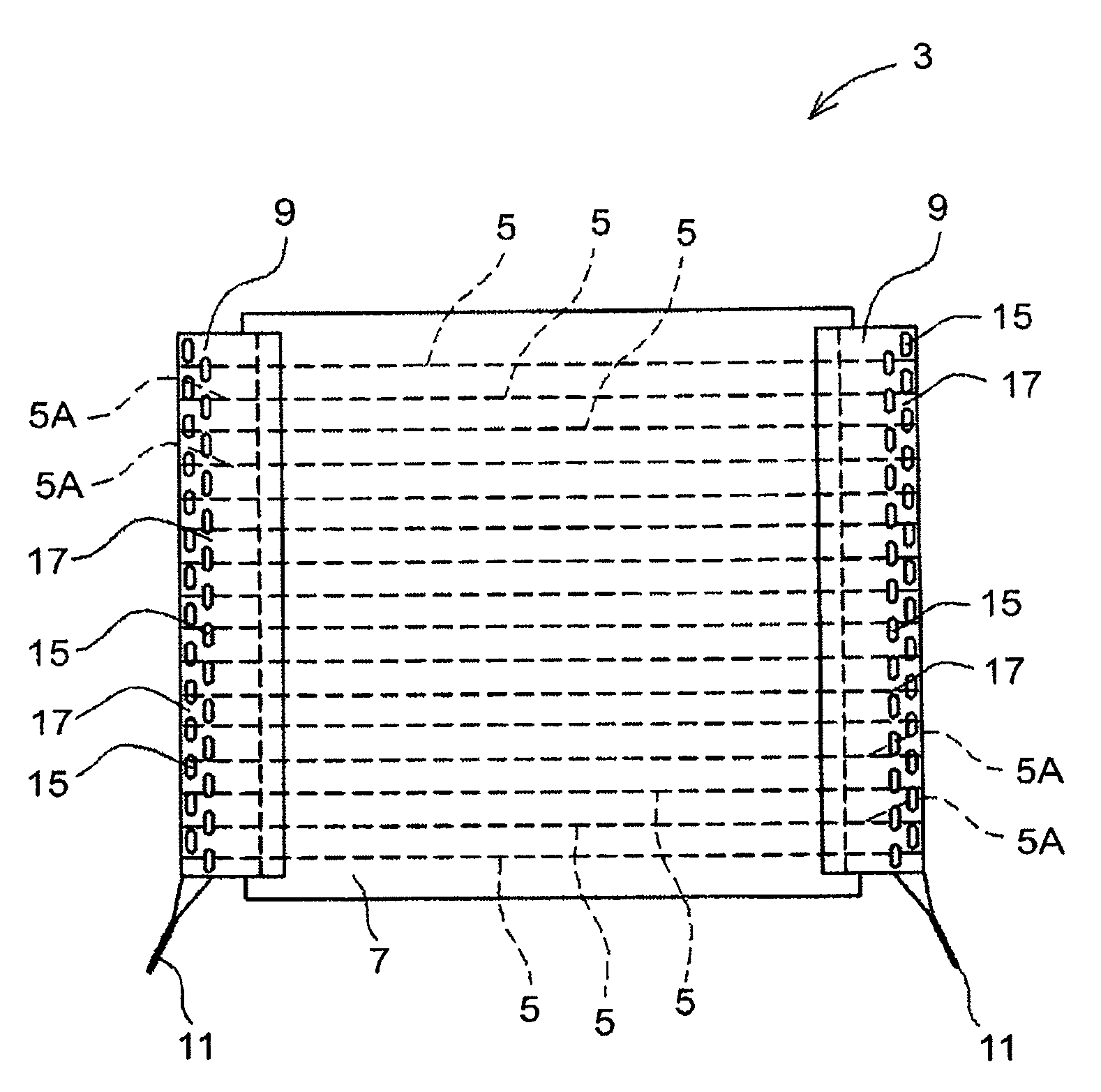
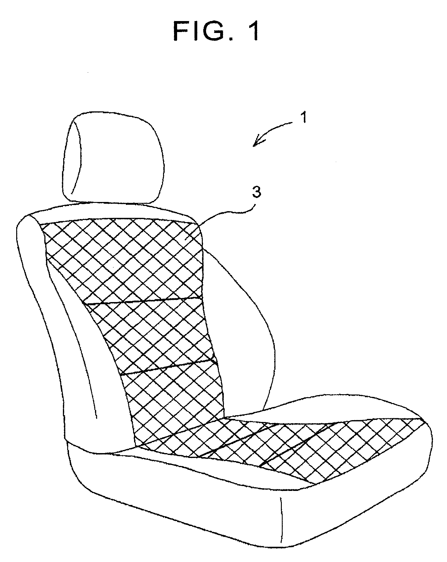
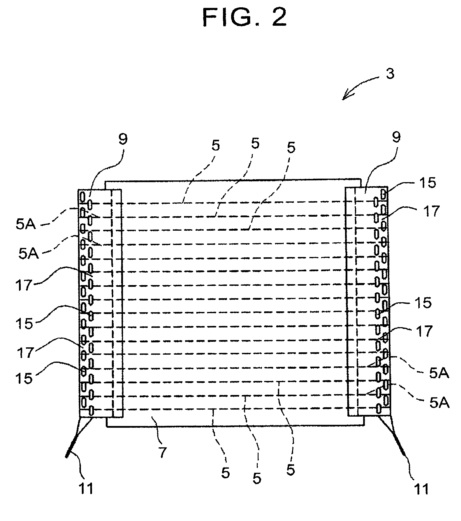
[0026]The invention will be further described in detail below with reference to the plurality of previously-mentioned drawings, giving non-limiting examples of typical example embodiments of the invention. Like reference characters are used to denote like parts throughout several drawings.

[0027]The matter illustrated here intended to describe, by way of example, exemplary modes and example embodiments of the invention. This matter is described for the purpose of providing what is considered to be a description that describes the principles and conceptual characteristics of the invention in a most effective and easily understandable manner. In this regard, the description, together with the drawings, makes clear to one skilled in the art ways in which several modes of the invention are actually realized, without intending to describe structural details of the invention beyond what is necessary to gain a fundamental understanding of the invention.

[0028]Hereinafter, the invention will ...


PUM


Abstract

A cloth material of the invention includes a cloth material main body that includes a plurality of conductive wires that generate heat by conduction, and a conductive connecting member that is provided on a side portion of the cloth material main body and electrically connects the plurality of conductive wires together. End portions of the plurality of conductive wires are exposed from the side portion of the cloth material main body so as to be exposed portions. The connecting member electrically connects the plurality of conductive wires together by being welded in a state sandwiching the exposed portions and the side portion of the cloth material main body. Welded portions formed by the welding are arranged alternately with non-welded portions, lined up in a line.

Description

BACKGROUND OF THE INVENTION[0001]1. Field of the Invention[0002]The invention relates to a cloth material. More particularly, the invention relates to a cloth material in which a connecting member for providing an electrical interconnection is attached to a side portion of a cloth material main body, without the flexibility of the cloth material itself being lost.[0003]2. Description of Related Art[0004]One known way to heat a seating surface of a seat in a vehicle, particularly a passenger vehicle or the like, is to use conductive wire for a portion of the constituent yarn of woven fabric or knit fabric that forms a cover, and pass current through this conductive wire to generate heat and raise the temperature. More specifically, a cloth material that includes conductive wire that generates heat by conduction is known, for example. A portion of the conductive wire in this cloth material in the length direction thereof is provided exposed to the outside from the cloth material. Japa...

Claims


Application Information

Patent Timeline
Patent Type & Authority Patents(United States)
IPC IPC(8): H05B3/34
CPCH05B3/342H05B2203/029H05B2203/014H05B2203/011
Inventor TADA, MASAO
Owner TOYOTA BOSHOKU KK
Why Eureka
Try Eureka