Centrifugal fan

a centrifugal fan and fan body technology, applied in the field of centrifugal fans, can solve the problems of air output quantity, input quantity and output quantity, affecting the entire heat dissipation performance,

Active Publication Date: 2015-12-08
DELTA ELECTRONICS INC
View PDF14 Cites 8 Cited by
  • Summary
  • Abstract
  • Description
  • Claims
  • Application Information

AI Technical Summary

Benefits of technology

[0009]In view of the foregoing subject, an object of the present invention is to provide a centrifugal fan that can prevent the air reflow and the pressure leakage, and can adjust the dimension of the inlet opening so as to increase the air input quantity, thereby enhancing the heat-dissipation performance.
[0026]In one embodiment of the present invention, a shape of the protrusion viewed in a rotational axis direction is annular or arc. As mentioned above, the centrifugal fan of the present invention is configured with a protrusion on at least one of the upper casing and the lower casing and surrounding the blade, so that the air entering from the inlet opening can be prevented from reflowing back to outside due to the pressure inside the casing. In addition, it is possible to configure multiple protrusions with different shapes on the casing to fit different environments or apply to the centrifugal fans of different dimensions. Moreover, the inlet opening of the centrifugal fan of the present invention includes a first inlet opening and a second inlet opening, so that it is possible to adjust the air input quantity of the centrifugal fan by adjusting the sizes of the first and second inlet openings.

Problems solved by technology

Thus, the air input quantity as well as the air output quantity may decrease, thereby affecting the entire heat-dissipation performance.

Method used


Image

  • Centrifugal fan
  • Centrifugal fan
  • Centrifugal fan

Examples


Embodiment Construction

[0037]The present invention will be apparent from the following detailed description, which proceeds with reference to the accompanying drawings, wherein the same references relate to the same elements.

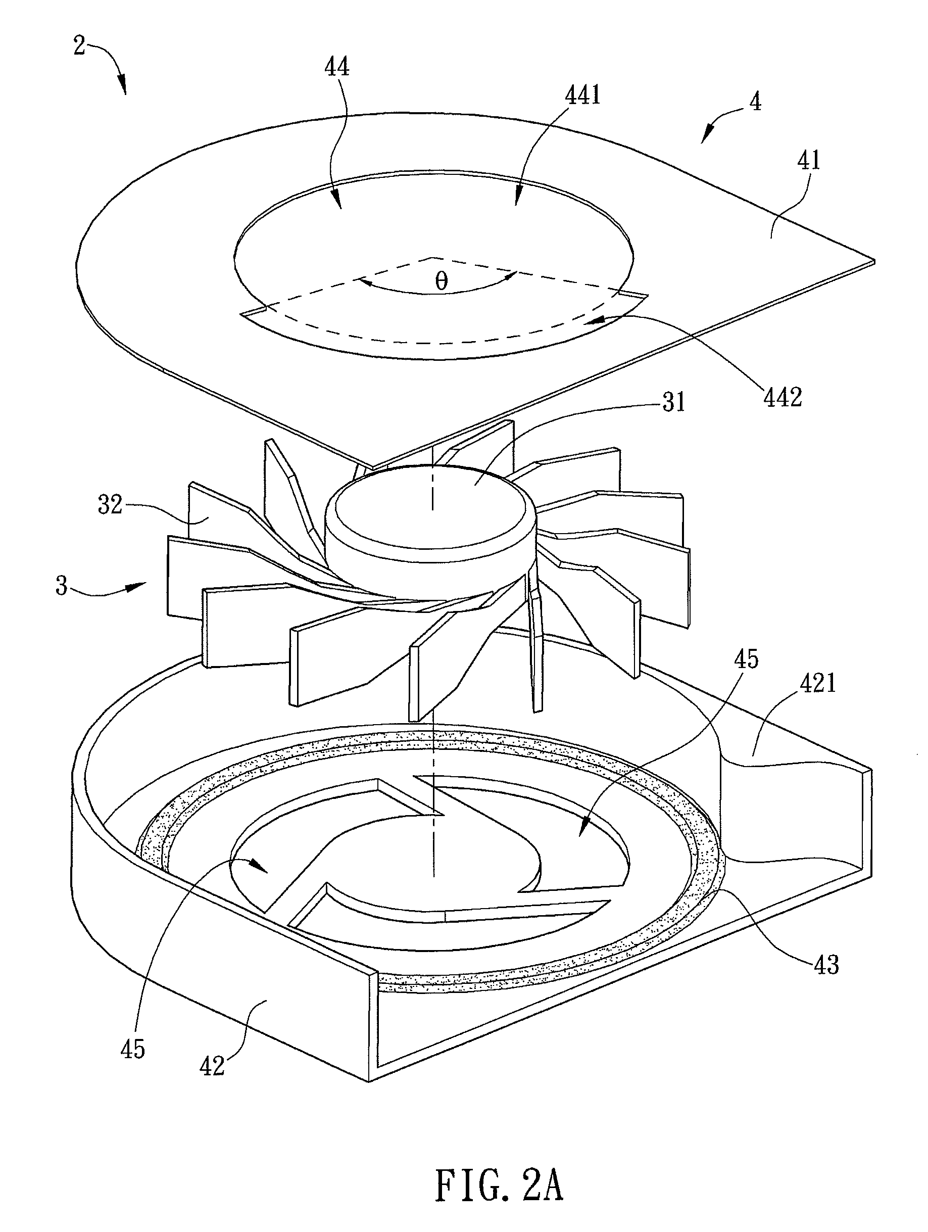
[0038]FIG. 2A is an exploded view of a centrifugal fan 2 according to a preferred embodiment of the present invention, and FIG. 2B is a perspective view of the assembled centrifugal fan 2 of FIG. 2A. Referring to FIGS. 2A and 2B, the centrifugal fan 2 includes an impeller 3 and a casing 4.

[0039]The impeller 3 includes a hub 31 and blades 32. The blades 32 are disposed surrounding the hub 31.

[0040]The casing includes an accommodation room for receiving the impeller 3. In the embodiment, the casing 4 includes an upper casing 41, a lower casing 42, at least one protrusion 43, and a first inlet opening 44. The upper casing 41 and the lower casing 42 are disposed opposite and connected to each other to form the accommodation room for receiving the impeller 3. The impeller 3 is disposed ins...


PUM


Abstract

A centrifugal fan comprises an impeller and a casing. The impeller includes a hub and a plurality of blades. The casing comprises an upper casing, a lower casing, at least one protrusion, a first inlet opening and a second inlet opening. The lower casing is disposed opposite to the upper casing and connected to the upper casing to form an accommodation room for receiving the impeller. The protrusion is formed on the upper casing and / or the lower casing inside the casing and immediately surrounds the blades. The first inlet opening is defined on the upper casing and comprises a primary inlet opening augmented by a secondary inlet opening. The second inlet opening is defined on the lower casing. The protrusion surrounds the first inlet opening and / or second inlet opening.

Description

CROSS REFERENCE TO RELATED APPLICATIONS[0001]This Non-provisional application claims priority under 35 U.S.C. §119(a) on Patent Application No(s). 100140875 filed in Taiwan, Republic of China on Nov. 9, 2011, the entire contents of which are hereby incorporated by reference.BACKGROUND OF THE INVENTION[0002]1. Field of Invention[0003]The present invention relates to a fan and, in particular, to a centrifugal fan.[0004]2. Related Art[0005]Since the electronic industries have been in progressive in the recent years, the electronic products may include many heat-generating electronic components, such as chips, that generate more and more heat. In order to effectively dissipate the redundant heat, it is usually to dispose a heat sink on the surface of the electronic component and then to install a centrifugal fan on the heat sink. The centrifugal fan can generate cooling airflow to remove the heat from the heat sink, thereby dissipating the heat of the electronic components.[0006]FIG. 1A...

Claims


Application Information

Patent Timeline
Patent Type & Authority Patents(United States)
IPC IPC(8): F04D29/16F04D25/08
CPCF04D29/162F04D25/08
Inventor LIN, HSIN-CHENHUANG, HSIANG-JUNG
Owner DELTA ELECTRONICS INC
Why Eureka
Try Eureka