Air spring with stepper motor driven pneumatic valve

Active Publication Date: 2015-12-15
INFINITY ENGINEERED PROD LLC
View PDF24 Cites 16 Cited by
  • Summary
  • Abstract
  • Description
  • Claims
  • Application Information

AI Technical Summary

Benefits of technology

[0009]Thus, an air spring arrangement is provided which allows a proper controlling of the pressure within the air spring volume. In particular, the position controllable drive in combination with a controllable valve allows controlling the opening grade of the controllable valve. In particular, the controllable valve may not only provide two discrete states, i.e. entirely open and entirely closed, but may also provide intermediate states. Thus, it is possible to smoothly control the pressure within the air spring volume, and the air spring volume as such, respectively. The height sensor may provide respective information on the state of the air spring arrangement, in particular the distance between the first mounting member and the second mounting member, so that based on the determined distance, the position controllable drive may control the controllable valve. With this respect, it is for example possible to maintain a particular distance, even if having changing environment conditions, or to automatically adapt the height according to respective requirements.
[0010]According to an exemplary embodiment of the invention, the controllable valve and the position controllable drive form an electrically powered motor driven valve. Thus, it is possible to properly drive the controllable valve by electric power, and in particular to control the opening grade of the controllable valve by the position controllable drive.
[0012]According to an exemplary embodiment of the subject invention, the characteristic between the position controllable drive and an opening grade of the controllable valve is predefined. Thus, it is possible to precisely control the controllable valve by the position controllable drive, as the opening grade of the controllable valve is known, when knowing the position of the position controllable drive. In particular, it is possible to precisely control the position controllable drive so as to precisely obtain an opening grade of the controllable valve, so that a feedback from the controllable valve for controlling purposes is not required any longer.
[0018]According to another exemplary embodiment of the present invention, the position controllable drive is a stepper motor and the controllable valve is a stepper motor driven pneumatic valve. Thus, it is possible to control the stepper motor with a controlling signal, for example a predefined number of impulses and to exactly know the stepper motor position, so that also the opening grade of the controllable valve is known. A stepper motor does not require a sensor for measuring the position of the rotor over the stator. Thus, without a feedback loop from the valve the opening grade of the valve is known, as it is predefined, e.g. via a look up table including the stepper motor rotor position versus the opening grade of the valve. Accordingly, it is possible to exactly control the opening grade of the controllable valve by selecting the respective proper pattern of a controlling signal for the stepper motor.
[0019]In accordance with a further exemplary embodiment of this invention, the position controllable drive is an electric motor with a position feedback, and the controllable valve is a position feedback motor driven pneumatic valve. Thus, the electrical motor may be driven by a driving signal, wherein the controlling unit may receive the position feedback of the electric motor, so as to provide a feedback loop to control the position of for example the rotor of the electric motor. By controlling the exact position of the rotor of the electric motor, also the exact opening grade of the controllable valve is known, so that it is possible to exactly control the opening grade of the controllable valve based on the position feedback of the electric motor as the position controllable drive.
[0024]According to another exemplary embodiment of this invention, the air spring arrangement further comprises a data bus, wherein at least two of the height sensor, the position controllable drive and the controlling device are communicatively connected to the data bus. Thus, it is possible to use a common data bus for easy communication between the units. In particular it is possible to transfer a height measurement value via the bus to the control unit and to transfer the control signal from the control unit to the position controllable drive via the same data bus. It should be noted that there may be provided an interface for coupling an external control unit to the data bus for providing e.g. set values etc., which can be entered by way of e keyboard or any other input device.

Problems solved by technology

As the controllable valve in combination with the position controllable drive has a self-holding characteristic, even the absence of power maintains the opening grade, so that the air spring arrangement may save a considerable amount of energy, in particular electrical energy.

Method used


Image

  • Air spring with stepper motor driven pneumatic valve
  • Air spring with stepper motor driven pneumatic valve
  • Air spring with stepper motor driven pneumatic valve

Examples


Embodiment Construction

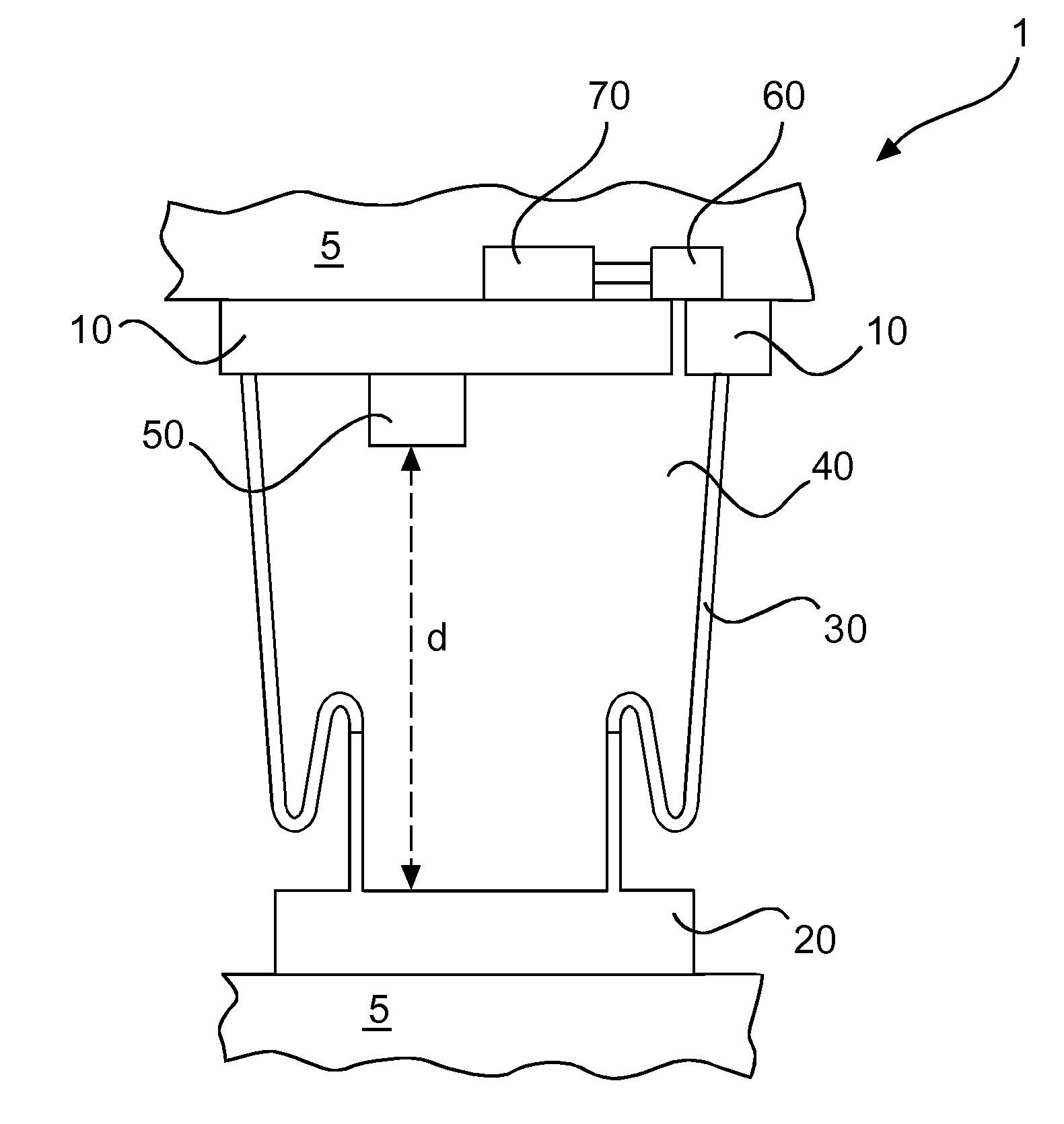
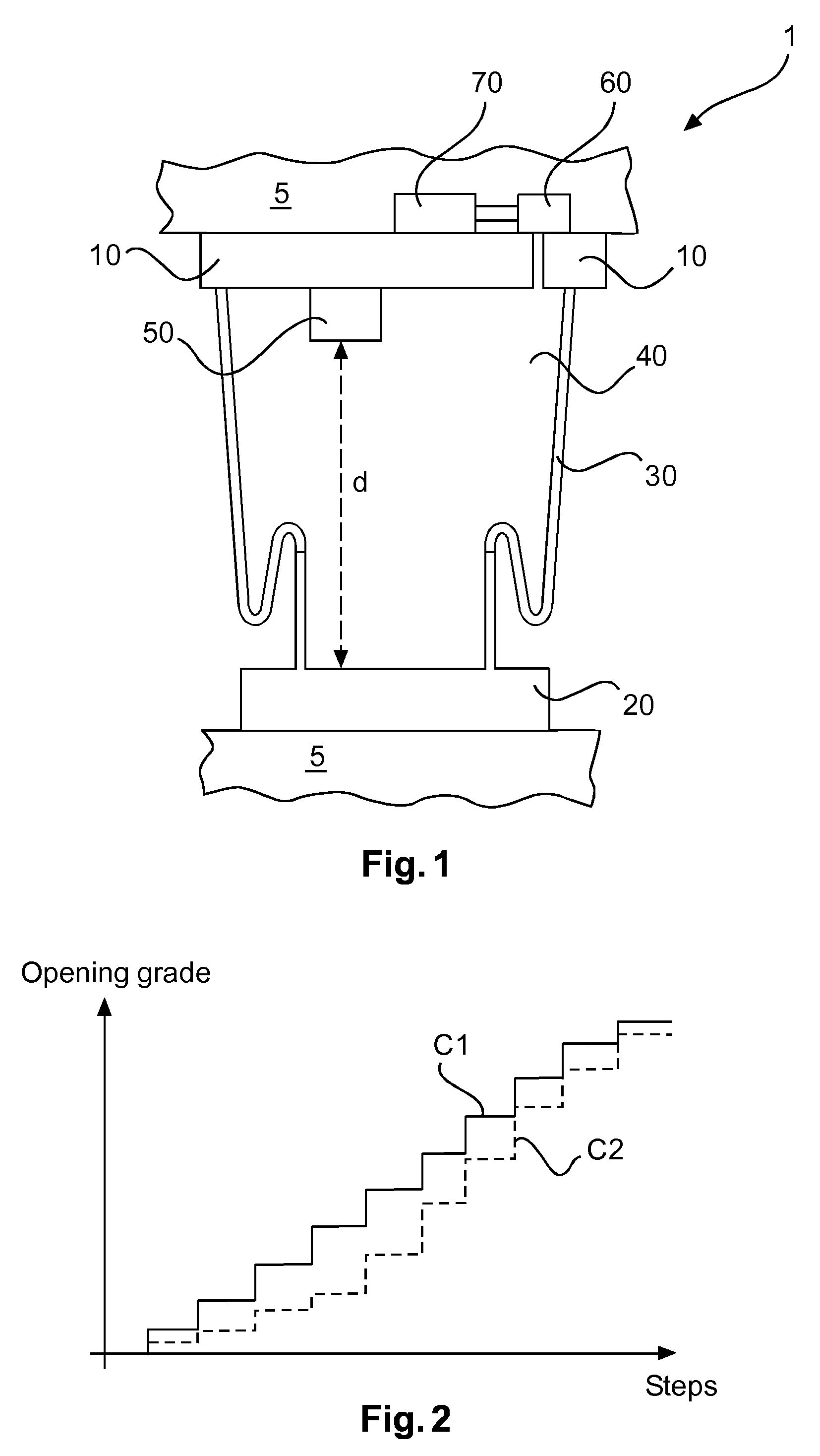
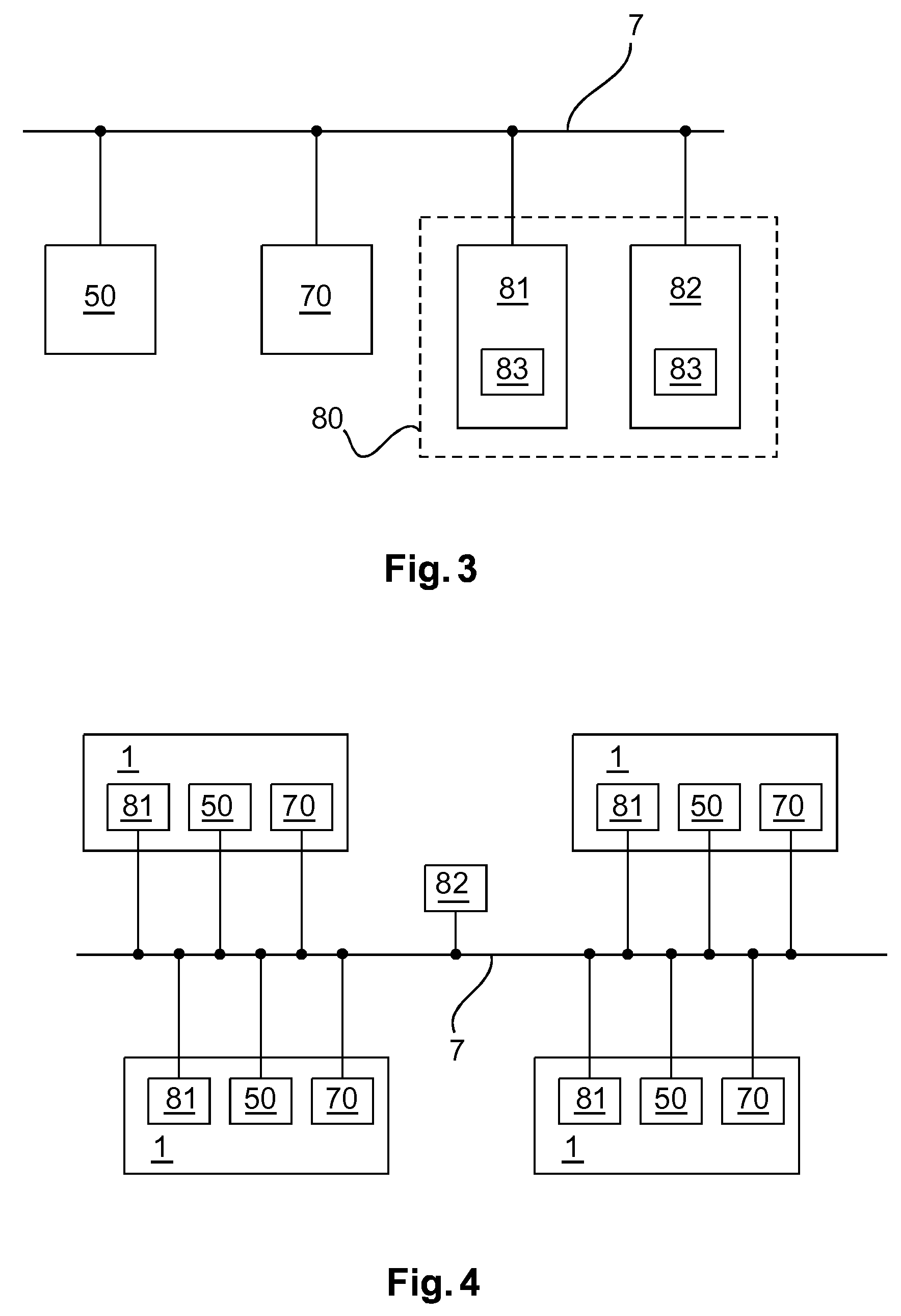
[0055]The present invention provides a combination of a height sensor, the use of a position controllable drive, e.g. a stepper motor, to opening and closing a pneumatic valve as a new and unique feature in a smart air spring device, which will be described in more detail in the following. The combination of an integrated height sensor and a stepper motor driven pneumatic valve is the combined use of two functional modules, a height sensor, and a stepper motor driven pneumatic valve in an air spring device. In general, the two functional modules are a height sensor and a position controllable drive driven valve in an air spring arrangement. The combination of such a position controllable drive and a controllable valve provides synergetic effects which allow a smart controlling of an air spring arrangement. In order to facilitate the communication between the sensor elements and the drive elements with a controlling unit, the functional modules may be provided with a build-in serial ...


PUM


Abstract

The subject invention reveals an air spring arrangement comprising: a first mounting member, a second mounting member, an air spring volume, a height sensor, a controllable valve, a position controllable drive, wherein the first mounting member and the second mounting member are arranged so as to mount the air spring volume to corresponding vehicle members, wherein the height sensor is arranged so as to sense a distance between the first mounting member and the second mounting member, wherein the controllable valve is arranged so as to connect the inside of the air spring volume with the outside of the air spring volume, wherein the position controllable drive is arranged so as to drive the controllable valve with respect to an opening grade of the controllable valve, and wherein the position controllable drive is controlled based on the sensed distance between the first mounting member and the second mounting member.

Description

[0001]This application claims benefit of European Patent Application Serial No. EP 13154685.5, filed on Feb. 8, 2013. The teachings of European Patent Application EP 13154685.5 are incorporated herein by reference in their entirety.FIELD OF THE INVENTION[0002]The present invention relates to an air spring and in particular to an air spring having a controllable valve and a position controllable drive for driving the controllable valve.BACKGROUND OF THE INVENTION[0003]Active air springs are used extensively in a wide range of industrial applications, but are mainly in transportation applications. Such “transportation applications” include, but are not limited to, use in passenger cars, vans, light trucks, commercial trucks, military vehicles, railroad locomotives and vehicles, military and commercial aircraft (airplanes), off-road or off-highway vehicles, farming equipment, construction equipment, mining equipment and vehicles, and other power-driven systems.[0004]A modern active air...

Claims


Application Information

Patent Timeline
Patent Type & Authority Patents(United States)
IPC IPC(8): B60G11/27B60G17/048B60G17/019B60G17/018F16F9/32B60G17/052B60G17/015F16F15/00F16F9/05
CPCB60G17/0485B60G17/0521B60G11/27B60G17/018B60G17/0155B60G17/0182B60G17/01933B60G17/0523F16F9/05F16F9/3292F16F15/002B60G2202/152B60G2202/44B60G2202/442B60G2206/011B60G2400/252B60G2500/204B60G2600/187B60G2600/1875B60G2600/76B60G2206/42B60G2202/41B60G2600/18F16F9/50
Inventor MAY, LUTZ
Owner INFINITY ENGINEERED PROD LLC
Why Eureka
Try Eureka