A tail gas treatment device for providing solid fuel conveying air

A solid fuel and exhaust gas treatment technology, applied in the combustion type, combustion method, lighting and heating equipment, etc., can solve the problems of uneven gas-solid two-phase flow, unstable combustion flame, fluctuation of heating effect, etc., to improve product quality and production capacity, ensuring stability, and reducing emissions

Active Publication Date: 2020-03-24
LAIR LIQUIDE SA POUR LETUDE & LEXPLOITATION DES PROCEDES GEORGES CLAUDE
View PDF7 Cites 0 Cited by
  • Summary
  • Abstract
  • Description
  • Claims
  • Application Information

AI Technical Summary

Problems solved by technology

[0011] The purpose of the present invention is to solve the above-mentioned problem of solid fuel conveying wind, especially the defect that the actual volume of the conveying wind is still changing even though the flow rate in the standard state of the conveying wind is stable through calculation compensation such as temperature and pressure, and the resulting difference between the conveying wind and the solid fuel The volume change of gas-solid two-phase flow causes unstable combustion flame and fluctuating heating effect. A tail gas treatment device is provided to realize constant temperature and constant pressure control of conveying air. It uses high-temperature industrial furnace combustion tail gas as raw material gas , after treatment, it can be used as solid fuel to transport air, which can not only solve the problem of high nitrogen oxides in the combustion tail gas of solid fuel combustion, but also overcome the problem of uneven gas-solid two-phase flow caused by the fluctuation of the air source of the transport air.

Method used


Image

  • A tail gas treatment device for providing solid fuel conveying air

Examples


Embodiment Construction

[0037] The technical solutions of the present invention will be further described below in conjunction with the drawings and embodiments.

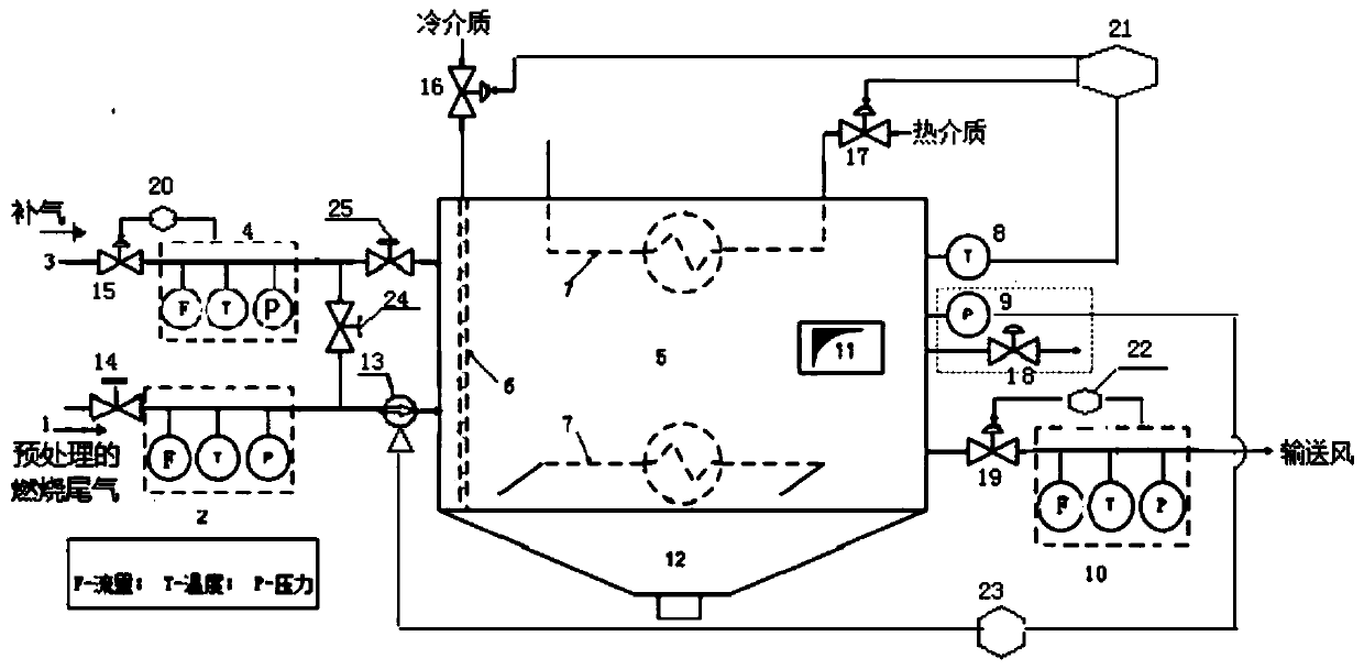
[0038] Such as figure 1 As shown, a kind of tail gas treatment device for providing solid fuel conveying wind of the present invention comprises:

[0039] Exhaust gas regulating chamber 5, the tail gas regulating chamber 5 includes: conveying air automatic temperature adjustment control system, pressure automatic adjustment control system;

[0040] The tail gas input pipe 1 and the air supply pipe 3 arranged at the inlet end of the tail gas regulating chamber; and

[0041] The delivery air duct outlet is arranged at the outlet end of the tail gas regulating chamber.

[0042] Wherein, the automatic temperature adjustment and control system of conveying air includes a temperature detection device 8 , a temperature adjustment device and a temperature controller 21 ; The temperature adjustment device can be equipped with heat exchange pipes...


PUM


Abstract

The invention discloses a tail gas treatment device used for providing solid fuel conveying air. The tail gas treatment device comprises a tail gas adjusting room, a tail gas input pipeline, an air supplementing pipeline and a conveying air pipeline outlet, wherein the tail gas adjusting room comprises a conveying air automatic temperature adjustment control system and a pressure automatic adjustment control system. The conveying air automatic temperature adjustment control system comprises a temperature detection device, a temperature adjustment device and a temperature controller; the pressure automatic adjustment control system comprises a pressure detection device, a pressure adjustment device and a pressure controller. With the tail gas treatment device, constant-temperature and constant-pressure control over conveying air is realized, the stability of the conveying air is guaranteed sufficiently, volume changes caused by temperature fluctuation are prevented from generating negative effects on the stability of gas and solid two-phase flows, and the tail gas treatment device is suitable for a high-temperature industrial boiler with petroleum coke powder or pulverized coal or other solid fuel being fuel and particularly suitable for a high-temperature industrial boiler combusting pure oxygen-solid fuel, and can be applied to the manufacturing fields of glass, metallurgy, cement, ceramic and others.

Description

technical field [0001] The invention relates to a high-temperature industrial furnace combustion tail gas treatment device, in particular to a tail gas treatment device for providing solid fuel conveying air. Background technique [0002] Solid fuels, such as petroleum coke powder and coal powder, have been widely used in glass furnaces, metallurgy, cement, ceramics and other manufacturing fields as cheap fuels. [0003] High-temperature industrial furnaces in glass, metallurgy, cement, ceramics and other manufacturing fields have widely used waste heat utilization, tail gas desulfurization and dust removal devices for environmental protection and energy saving. However, the treatment cost of nitrogen oxides is still relatively high, and taking control measures from the source of nitrogen oxides has certain unique advantages. [0004] Taking petroleum coke fuel as an example, due to its own characteristics and complex composition, the solid fuel brings various problems to u...

Claims


Application Information

Patent Timeline
Patent Type & Authority Patents(China)
IPC IPC(8): F23G7/06F23G5/50F23G5/44
CPCF23G5/44F23G5/50F23G7/06
Inventor 阎韬瑞米·奇亚瓦刘奔
Owner LAIR LIQUIDE SA POUR LETUDE & LEXPLOITATION DES PROCEDES GEORGES CLAUDE
Why Eureka
Try Eureka