Dual rod mooring pendant apparatus

a technology of pendant apparatus and rod rod, which is applied in the direction of mine sweeping, hoisting equipment, vessel construction, etc., can solve the problems of unassisted boaters, difficulty in mooring their boats, and difficulty created in trying to tie the rope to the buoy ring, so as to improve the current device and apparatus, and ensure safe and convenient docking.

Active Publication Date: 2015-12-15
CARDARELLI VENANZIO +1
View PDF23 Cites 7 Cited by
  • Summary
  • Abstract
  • Description
  • Claims
  • Application Information

AI Technical Summary

Benefits of technology

[0005]The present invention improves on current devices and apparatus and provides a safe and convenient means for docking a boat to a mooring structure using a dual rod mooring pendant apparatus. The apparatus releasably couples or decouples to an eyelet on the bow of the boat or to a buoy. The apparatus includes a clip attachment front end that may open or close for attachment or release. The front end includes a hook attachment base which is connected by a wedge onto the backbone of a hook, with the hook attachment clip base having a pair of pull line apertures and a pair of rod channels defined in the base. The hook has a movable arm for opening and closing, a grasping end on the hook for receiving the movable arm, and a ring section having an opening for tying a mooring line. The wedge is connected to the hook attachment base with 1 inch truncated screws. Each truncated screw having a partially smooth shank starting from the head of the screw. A fixed guide provides stability and guidance and has a pair of mooring line guidance extensions defining an opening for

Problems solved by technology

Because of the difficulty in securing a mooring rope to a relatively remote eye member, such as one found on the bow of a boat, the boater often omits this procedure and only ties the boat to the cleats on the top surface of the boat.
The difficulty created in trying to tie the rope to the buoy ring may be just as hard because the boater must reach down for the buoy and then often must pull it up to tie the line.
The main problem that is encountered in tying a mooring rope to the ring on the bow of a boat is usually due to the awkward position in which most bow rings are located.
Reaching over and trying to reach the bow ring can be very hazardous to a boater, especially in rough wa

Method used


Image

  • Dual rod mooring pendant apparatus
  • Dual rod mooring pendant apparatus
  • Dual rod mooring pendant apparatus

Examples


Embodiment Construction

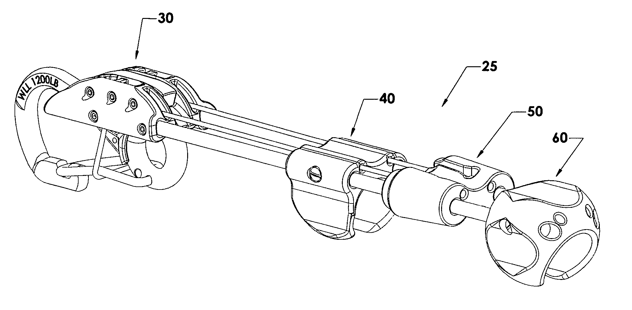
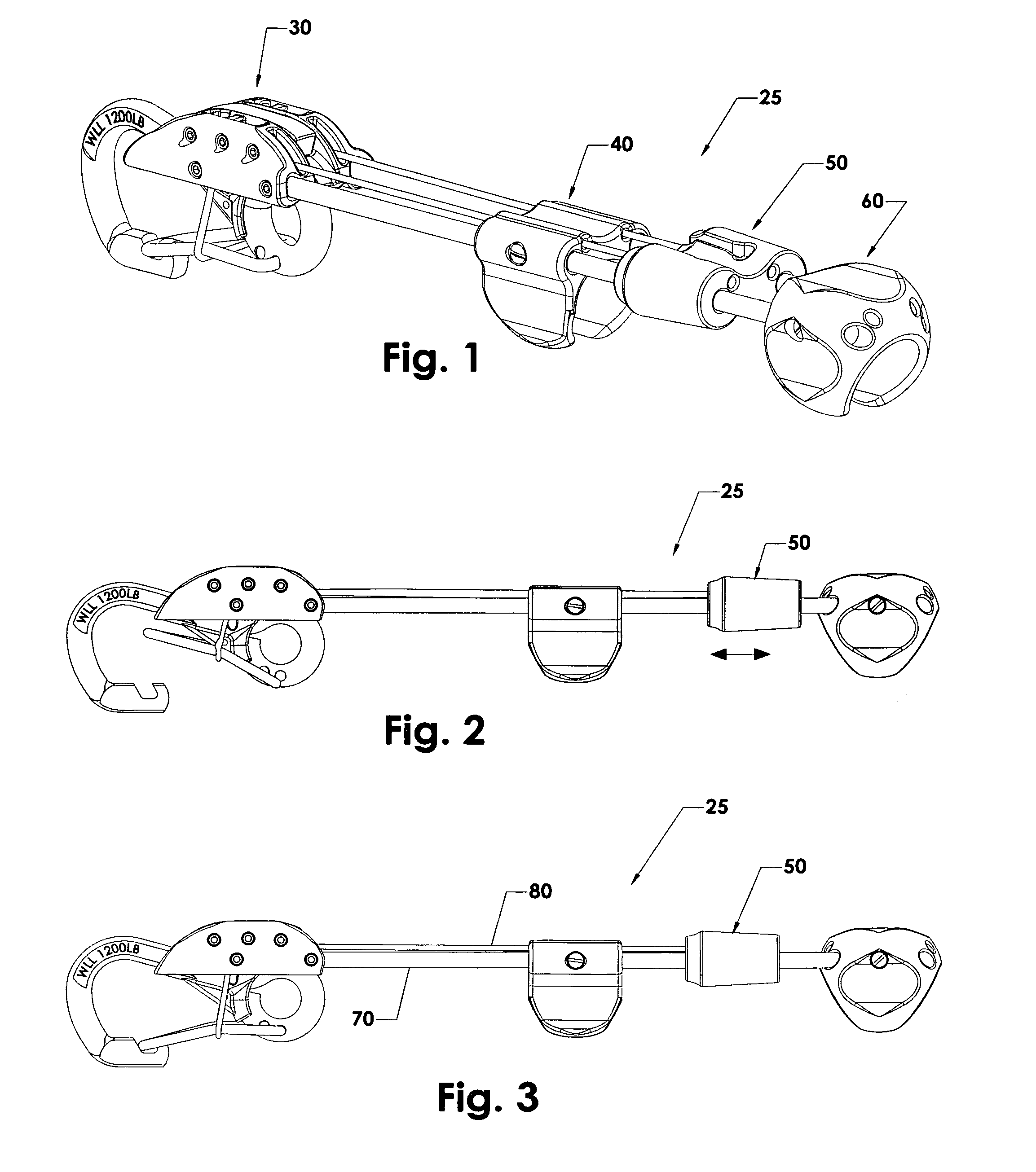
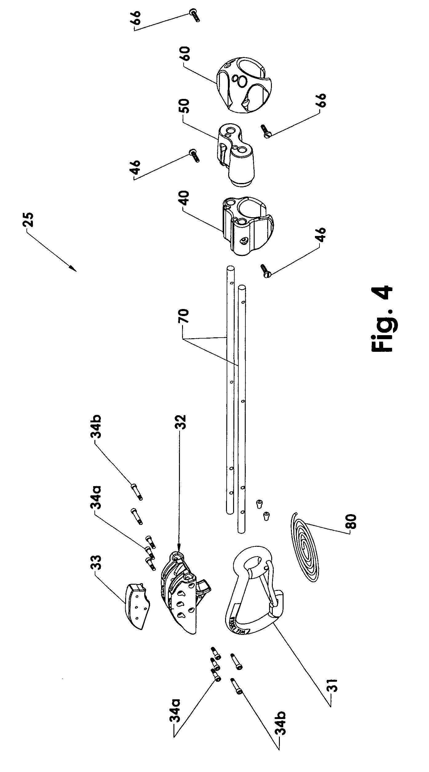
[0030]The preferred embodiment of the invention will now be described with reference to the Figures. Some terms used in the description and the appended claims are defined below. Referring to FIGS. 1-3, the illustrated mooring pendant apparatus 25 is comprised of the following portions: an attachment front end 30; a fixed guide 40; a slide 50; a handle 60; a pair of interconnecting rods 70; and a pair of pull lines 80. Actually, the pull lines are a continuous single line that is wrapped around the movable arm. Important considerations in the design of the invention are the materials, size, length, and weight since the apparatus is subject to harsh conditions and must be used by a single boater.

[0031]The boat ring (found on the boat and therefore not shown here) may have several functions, but for the purpose of the present invention the focus is on its location on the boat. The boat ring is placed nearer to the water to lower its' center of gravity and rotation, therefore using the...


PUM


Abstract

A dual rod apparatus for coupling and decoupling of attachment hooks to facilitate the mooring of a boat. The apparatus comprises an attachment front end which includes a hook, a hook attachment base connected onto the hook by a wedge. The hook attachment base having a pair of pull line apertures and a pair of rod channels. The apparatus includes a pair of rods, a pair of pull lines. A fixed guide provides stability for the rods and pull lines. A handle controls the apparatus. A slide is positioned between the guide and handle and opens the hook when the slide is pulled with sufficient force to overcome locking tensions placed by the hook.

Description

CROSS-REFERENCE TO RELATED APPLICATIONS[0001]This application relates to Provisional U.S. Application No. 61 / 795,791, on Oct. 26, 2012, for a Dual Rod Pendant Apparatus, the disclosure of which is incorporated by reference herein in its entirety.FIELD OF THE INVENTION[0002]This invention relates to a dual rod apparatus for coupling and decoupling of attachment hooks to facilitate the mooring of a boat. More specifically, the apparatus allows for easier attachment of a mooring line to the bow of a boat while using a dual rod handle.BACKGROUND OF THE INVENTION[0003]Pleasure boats, such as yachts and small boats, are often moored to either a dock rail or a mooring buoy. The mooring line is tied around the dock rail or through a mooring ring on a buoy. Preferably the mooring line is tied to a ring or eye member that is found on the bow of the boat. Because of the difficulty in securing a mooring rope to a relatively remote eye member, such as one found on the bow of a boat, the boater o...

Claims


Application Information

Patent Timeline
IPC IPC(8): B63G7/04B63B21/54B63B21/04B66F19/00
CPCB63B21/04B63B21/54
Inventor CARDARELLI, VENANZIOWOLF, RONALD A
Owner CARDARELLI VENANZIO
Why Eureka
Try Eureka