
Smart traffic sign system and method

a traffic sign and intelligent technology, applied in the field of smart traffic sign system and method, can solve the problems of unclear and dangerous response of the driver, uneven traffic flow control, etc., and achieve the effect of increasing vehicle and driver safety

Active Publication Date: 2015-12-15
BRIGHTWAY VISION
View PDF34 Cites 47 Cited by
  • Summary
  • Abstract
  • Description
  • Claims
  • Application Information

AI Technical Summary

Benefits of technology

The present patent relates to a safety system for vehicles that uses infrared signals to identify different road indicators and their surroundings, making it easier for drivers to see and respond to potential hazards in advance. This system can be added onto existing vehicles and work in conjunction with existing sensors and alert systems to improve safety and driving experience.

Problems solved by technology

Common dangerous example is a vehicle approaching a traffic light indicating a “Green” light, while the vehicle is in a short to none stopping distance from the traffic light; light indication has changed to “Red” leaving the driver in an unclear and dangerous situation how to respond.
In these and other instances, the driver may delay response to such conditions and / or the driver may hesitate or otherwise become confused in reacting, i.e., wrongfully, accelerating, decelerating, applying brakes etc., of the vehicle thereby further risking the driver and / or the driver's surroundings.
Another aspect may be an unevenly traffic flow control due to unexpected acceleration / deceleration of vehicles approaching traffic sign and / or traffic light indications.
Another drawback of '428 B2 patent is directly associated with the mass infrastructure that may be required to distribute the mesh of wireless transmitters along the road.
The system described in '828 B1 patent does not offer multiple indication areas (e.g. prior approaching vehicle) with different optical information as required, for example, when coupled to a traffic light indication.
Notwithstanding their availability, such prior art systems have not been able to provide adequate solutions to the above shortcomings

Method used


Image

  • Smart traffic sign system and method
  • Smart traffic sign system and method
  • Smart traffic sign system and method

Examples


Embodiment Construction

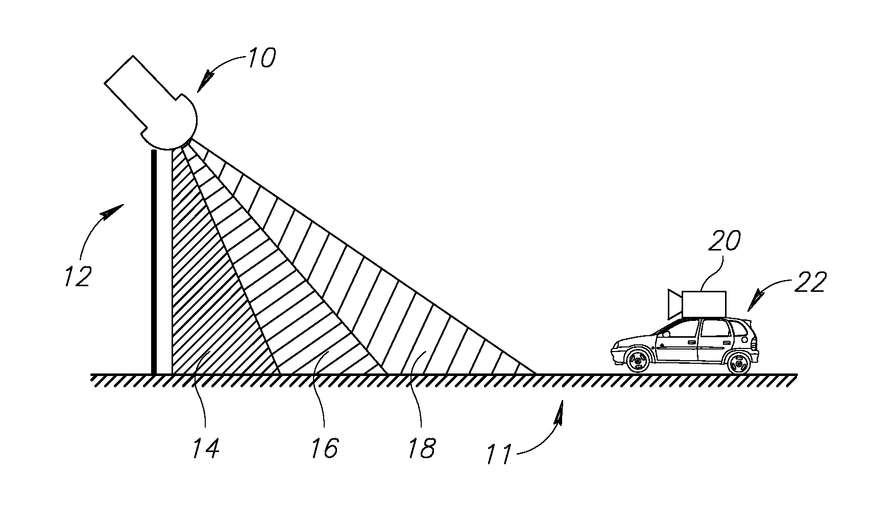
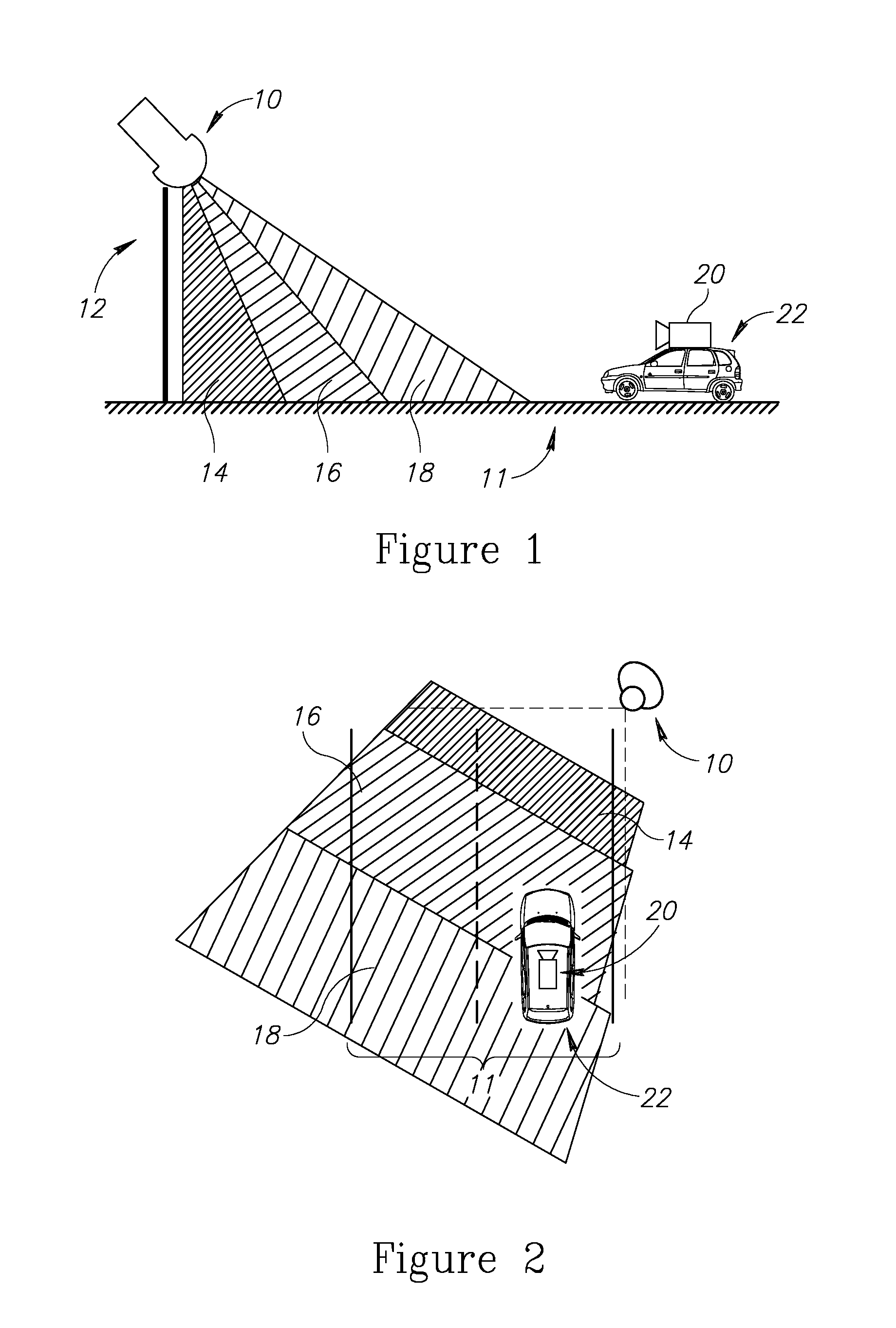
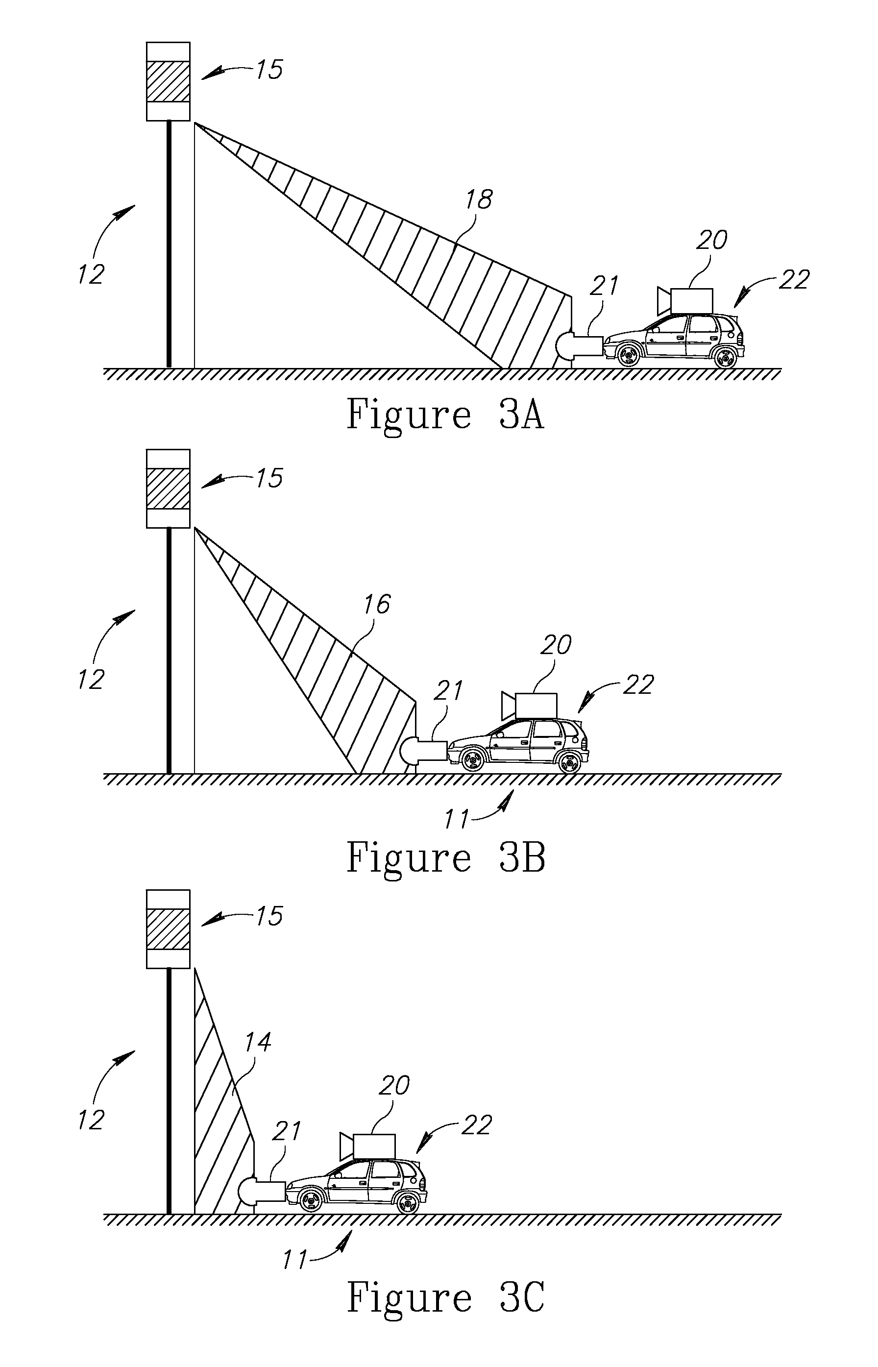
[0027]FIG. 1 and FIG. 2, present an illuminator module 10 positioned near or on a traffic sign 12, providing a clear FOI to incoming traffic, such as vehicle 22 with a receiver module 20 traveling on a route 11. Illuminator module 10 FOI may be divided to zones 14, 16, and 18. Traffic sign 12 may be any conventional and known traffic sign, such as a stop sign, yield sign and alike, whereby each sign may have its own illumination characteristics and FOI zones 14, 16, and 18, respectively, such as provided by illuminator module 10. Accordingly, each of the signs and its associated FOI zones 14, 16, and 18 having unique electro-optical characteristics typifying the type of sign used, typifying the distance to sign, typifying the closing velocity to sign and alike. In other words, a stop sign utilizes an illuminator module having FOI zones 14, 16, and 18 typified by particular electro-optical characteristics, while a yield sign may utilize an illuminator module 10 having other types of ...


PUM


Abstract

A system for increasing awareness of a driver to traffic-signs on the road is provided herein. The system includes: a sensor attached to a vehicle and configured to determine a type of one or more traffic-signs that are present in a scene containing the vehicle, wherein at least some of the traffic-signs are time-variant traffic-signs which present time-variant visual indicators; and a controller configured to: monitor and analyze, in real time: relative metrics indicative of one or more spatial relations between the vehicle and the one or more detected traffic-signs; and temporal data associated with the time-variant visual indicators of the time-variant traffic-signs; apply one or more decision functions to at least two of: the detected one or more traffic-signs and to the monitored relative metrics, and the temporal data associated with the time-variant visual indicators, so as invoke an action selected from a predefined set of actions.

Description

CROSS-REFERENCE TO RELATED APPLICATIONS[0001]This application is a National Phase Application of PCT International Application No. PCT / IL2012 / 050493, International Filing Date Dec. 3, 2012, entitled “SMART TRAFFIC SIGN SYSTEM AND METHOD”, published on Jun. 13, 2013 as International Publication Number WO 2013 / 084225, claiming priority of U.S. Patent Application No. 61 / 566,700, filed Dec. 5, 2011, both of which are incorporated herein by reference in their entirety.BACKGROUND[0002]1. Technical Field[0003]The present invention relates to systems and method adapted to improve and aid driving of motor vehicles by users, as well as, increase awareness of the driver to traffic signs and the driver's surroundings.[0004]2. Discussion of the Related Art[0005]While driving a vehicle, drivers may, at times, become less aware or otherwise become oblivious to certain road conditions, as could happen during a mundane and / or a monotonous drive, or even when the attention of the driver may be divert...

Claims


Application Information

Patent Timeline
Patent Type & Authority Patents(United States)
IPC IPC(8): G08G1/16G08G1/09G01S17/88G01S17/08G08G1/0967
CPCG08G1/096758G08G1/096783G08G1/09G01S17/08G01S17/88G08G1/096716
Inventor GRAUER, YOAVDAVID, OFERDAVID, YA'ARAGARTEN, HAIMKRELBOIM, ALONLIFSHITS, SHARONSHEICH, OREN
Owner BRIGHTWAY VISION
Learn More