

Cabinet in a milking parlour
a cabinet and milking parlour technology, applied in the field of milking parlour cabinets, can solve the problems of time-consuming and expensive manufacturing, difficult to swing the cabinet door to an open position, and insufficient space for installation, repair or servi
- Summary
- Abstract
- Description
- Claims
- Application Information
AI Technical Summary
Benefits of technology
Problems solved by technology
Method used
Image

Examples
Embodiment Construction
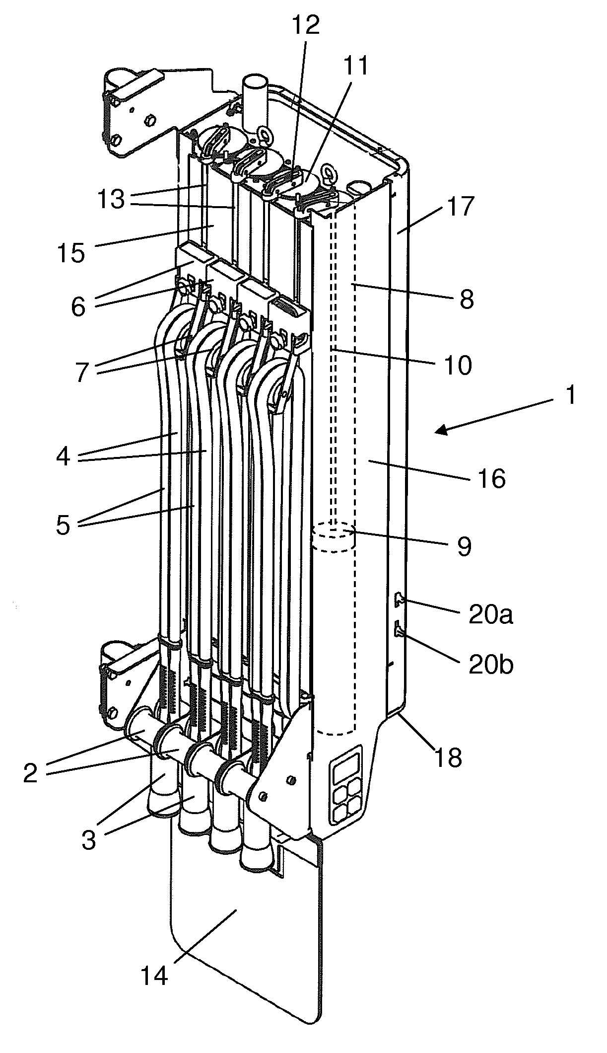
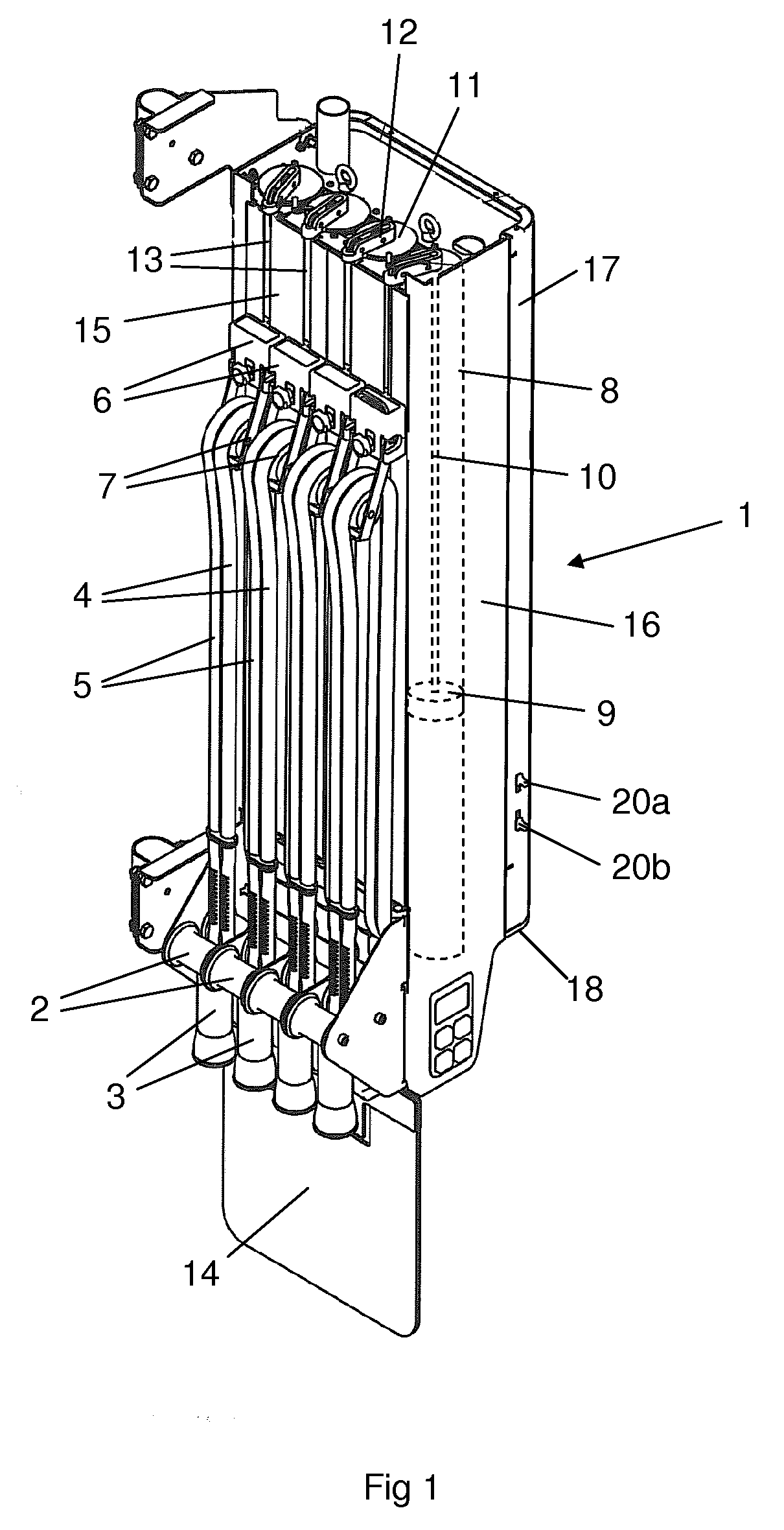
[0022]FIG. 1 shows a teat cup magazine 1. The teat cup magazine 1 is to be arranged in or in the vicinity of a milking stall in a milking parlour for cows. The teat cup magazine 1 comprises four stationary arranged rolling elements 2, each defining a storing position for a teat cup 3 in the teat cup magazine 1. The storing positions of the teat cups 3 are located in a row at a lower end portion of the teat cup magazine 1. Each teat cup 3 is connected to a milk tube 4 and a pulse tube 5. The milk tube 4 and the pulse tube 5 are supported by a movably arranged guiding element 6. Each guiding element 6 comprises a rolling member 7 to be in contact with the milk tube 4 and the pulse tube 5. The milk tube 4 and the pulse tube 5 have a substantially vertical extension between the stationary arranged rolling elements 2 and the movably arranged rolling member 7. The rolling members 7 define the highest position of the milk tubes 4 and the pulse tubes 5 in the teat cup magazine 1. When a gui...
PUM
 Abstract
Description
Claims
Application Information