LED lighting driver

a technology of led lighting and led output power, which is applied in the direction of electric lighting sources, electroluminescent light sources, and use of semiconductors. it can solve the problems of large power regulation issues, large illumination power, and large disparity of led output power of conventional linear led lighting drivers, and achieve the effect of constant output power

Inactive Publication Date: 2015-12-22
GREEN MARK TECH
View PDF22 Cites 4 Cited by
  • Summary
  • Abstract
  • Description
  • Claims
  • Application Information

AI Technical Summary

Benefits of technology

[0042]Accordingly, the present invention is directed to an LED lighting driver which can maintain constant output power against input AC voltage variation. Another aspect of the present invention is to provide a solution to maintain the LED current at a constant value throughout a line cycle.

Problems solved by technology

However, recent attempts to implement the conventional linear driver into actual LED lighting products have encountered a major power regulation issue.
Namely, a linear LED lighting driver supplies insufficiency illumination power when the utility AC voltage is lower, whereas it supplies excessive illumination power when the utility AC voltage is higher.
This issue arises mainly due to there are various utility AC voltages around the world.
Unfortunately, a conventional linear LED lighting rated at 500 lumens in 120Vrms utility AC voltage countries, such as USA and Canada, will only provide about 370 lumens in 100Vrms utility AC voltage countries, such as Japan.
This disparity of LED output power is a major drawback of conventional linear LED lighting drivers.
Furthermore, it is calculated that the actual input power, Pin, is increased to 6.16 W. This excessive power dissipation will make the LED sections to heat up substantially.
In general, LED sections running at elevated temperature will degrade their reliability and usable life.
In summary, conventional LED lighting drivers have some limitations.
The first limitation is poor output power regulation against AC line voltage variation.
The second limitation is that LED current will drop to zero when the rectified sinusoidal voltage VIN drops below the forward voltage of the first LED section during a half line cycle.

Method used


Image

  • LED lighting driver
  • LED lighting driver
  • LED lighting driver

Examples


Embodiment Construction

[0051]Reference will now be made in detail to the present embodiments of the invention, examples of which are illustrated in the accompanying drawings. Wherever possible, the same reference numbers are used in the drawings and the description to refer to the same or like parts.

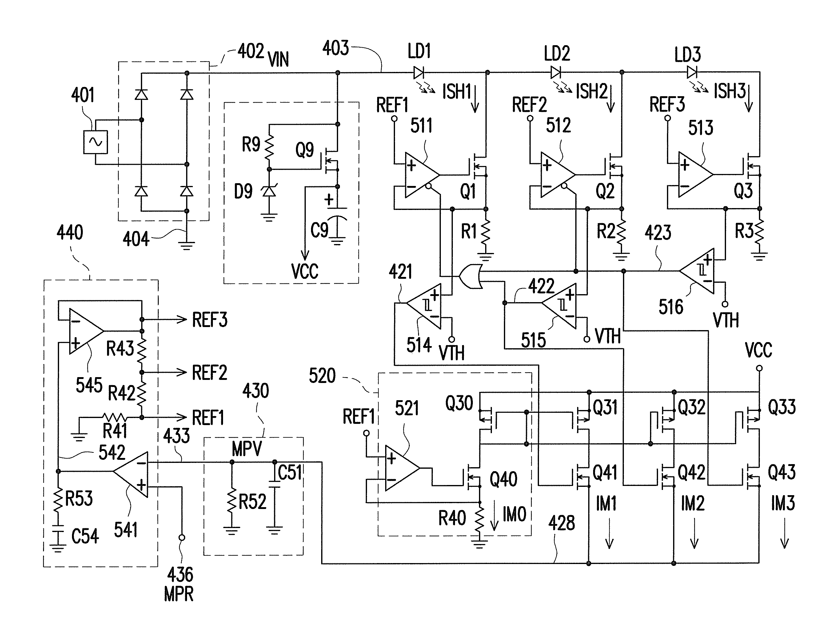
[0052]In order to have a more accurate estimate of the average LED output power, the present invention incorporates a weighted current mirror array and a mean power integrator to monitor the actual average output power in a real-time manner. FIG. 4 shows a preferred embodiment of the present invention. In addition to the LED sections and shunt regulators of a conventional linear LED lighting driver, it further includes a weighted current mirror array 420, a mean power integrator 430, a current reference generator 440, and a mean power reference (MPR) value 436.

[0053]The voltage source 401 represents the utility AC voltage input. Bridge rectifier 402 rectifies the utility AC voltage input and outputs the rectif...


PUM


Abstract

A light-emitting diode (LED) lighting driver is provided, which includes a bridge rectifier, multiple LED sections, multiple shunt regulators, a weighted current mirror array, a mean power integrator, and a reference generator. The bridge rectifier provides a rectified sinusoidal voltage. The LED sections are coupled in series and coupled to the rectified sinusoidal voltage. Each shunt regulators regulates a shunt current flowing out from the LED sections according to a current reference value. The weighted current mirror array provides a plurality of copy currents. Each copy currents tracks the conduction time of one shunt regulator and also tracks the instantaneous output power of the LED sections. The mean power integrator provides a mean power value by integrating the copy currents. The reference generator provides the current reference values. Each current reference values is directly proportional to the difference between a mean power reference value and the mean power value.

Description

BACKGROUND OF THE INVENTION[0001]1. Field of the Invention[0002]The present invention relates to a light emitting diode (LED) lighting driver. More particularly, the present invention relates to an LED lighting driver including a feedback control loop based on the mean output power of the LED sections.[0003]2. Description of the Related Art[0004]Linear light-emitting diode (LED) lighting drivers have been proposed in recent years. They can be directly connected to utility alternating current (AC) voltage and power up an array of LED devices without the need for bulky and expensive switching-mode LED drivers.[0005]However, recent attempts to implement the conventional linear driver into actual LED lighting products have encountered a major power regulation issue. Namely, a linear LED lighting driver supplies insufficiency illumination power when the utility AC voltage is lower, whereas it supplies excessive illumination power when the utility AC voltage is higher.[0006]This issue ari...

Claims


Application Information

Patent Timeline
Patent Type & Authority Patents(United States)
IPC IPC(8): H05B37/00H05B33/08H05B44/00
CPCH05B33/083Y02B20/348H05B45/48Y02B20/30
Inventor LIU, KWANG-HWALIANG, SHEN-YAO
Owner GREEN MARK TECH
Why Eureka
Try Eureka