Driving low voltage brushless direct current (BLDC) three phase motors from higher voltage sources

a three-phase, low-voltage technology, applied in the direction of dc motor rotation control, dynamo-electric converter control, electric controller, etc., can solve the problems of reducing efficiency, affecting the operation of the motor, so as to achieve constant output power, wide input voltage variation, and efficient power transfer

Active Publication Date: 2014-04-15
MICROCHIP TECH INC
View PDF55 Cites 3 Cited by
  • Summary
  • Abstract
  • Description
  • Claims
  • Application Information

AI Technical Summary

Benefits of technology

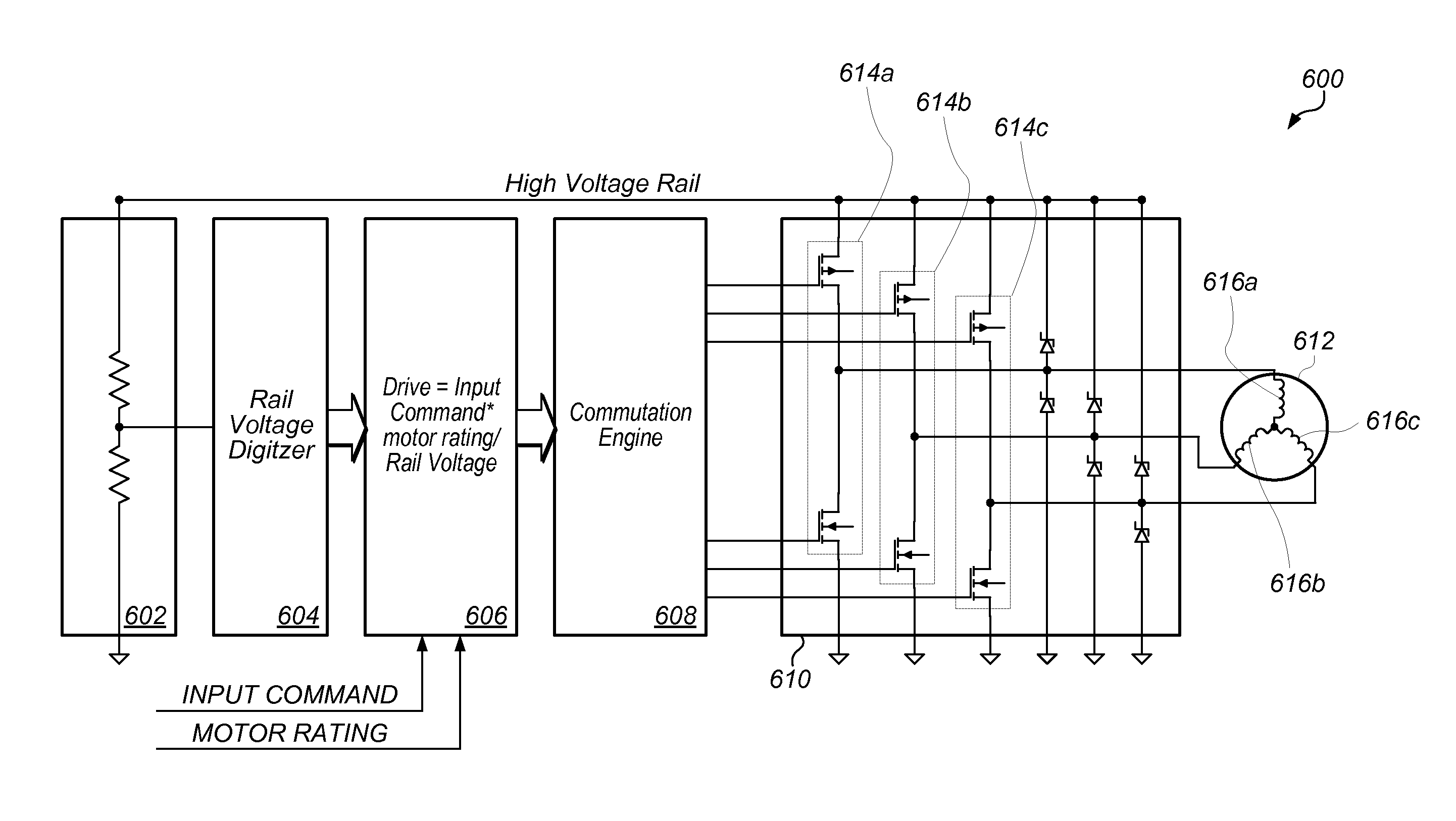
[0017]Operation of the motor may then be controlled based on the one or more time values and the PWM duty cycle. More specifically, the plurality of electromagnets on the stator may be driven by periodic bursts of current whose frequency and power may be specified by the PWM duty cycle in such a way as to drive the rotor at a particular rotational speed, while the one or more time values may determine the commutation timing of the electromagnets on the stator, such that the electromagnetic field of the stator may remain substantially in optimal alignment with the rotor, effecting an efficient transfer of power to the rotor at that particular rotational speed.
[0018]The above operations may repeat over a plurality of iterations. In one embodiment, the next zero crossing value from the previous iteration is used as the first expected zero crossing value in the next iteration. In one set of embodiments, the stator coil in the respective electromagnets on the stator is used as the inductive element that a regulator, such as a buck regulator can use to regulate the current. While a regulator may typically regulate the current in the inductive element as a means of regulating the output voltage, in various embodiments disclosed herein, such regulators may be used specifically with the intent of regulating the current in the stator coils, without any intent of regulating the output voltage. The duty cycle to the coils may then be calculated based on both the input command, and the rail voltage used for powering the drivers that drive the plurality of electromagnets, as measured in real time. This allows for wide variation of input voltage, while maintaining a relatively constant output power to the motor drive. Thus, in addition to basing the final PWM duty cycle on the input command, another variable, the rail voltage may also be used to scale the final PWM duty cycle that is applied to the stator coils, to effectively scale the maximum current through the stator coils to the same magnitude current that would be expected to flow through the coils if the rail voltage were the rated (nominal) fan voltage, and not the actual rail voltage.

Problems solved by technology

The use of brushes creates friction in the motor and leads to maintenance issues and reduced efficiency.
One issue oftentimes taken into consideration when designing motors, more specifically brushless motors, is the power required to operate the motor.
However, in certain cooling applications the desired power is not always available, oftentimes requiring the use of a non-ideal regulator to reduce the available voltage level to a level useable by the fan being driven by the motor.
Most current solutions are limited to developing very efficient buck regulators capable of high input voltages at relatively low current, and producing low voltage, high current outputs.
Anything less than 100% efficiency results in energy being lost in the conversion from one rail voltage to another.
Further losses are encountered during the commutation process, as there are finite losses in the switching transistors that may be used in commutation.
In many cases this would represent less than the desired efficiency.

Method used


Image

  • Driving low voltage brushless direct current (BLDC) three phase motors from higher voltage sources
  • Driving low voltage brushless direct current (BLDC) three phase motors from higher voltage sources
  • Driving low voltage brushless direct current (BLDC) three phase motors from higher voltage sources

Examples


Embodiment Construction

FIGS. 1A and 1B—Exemplary Fan and Fan Motor

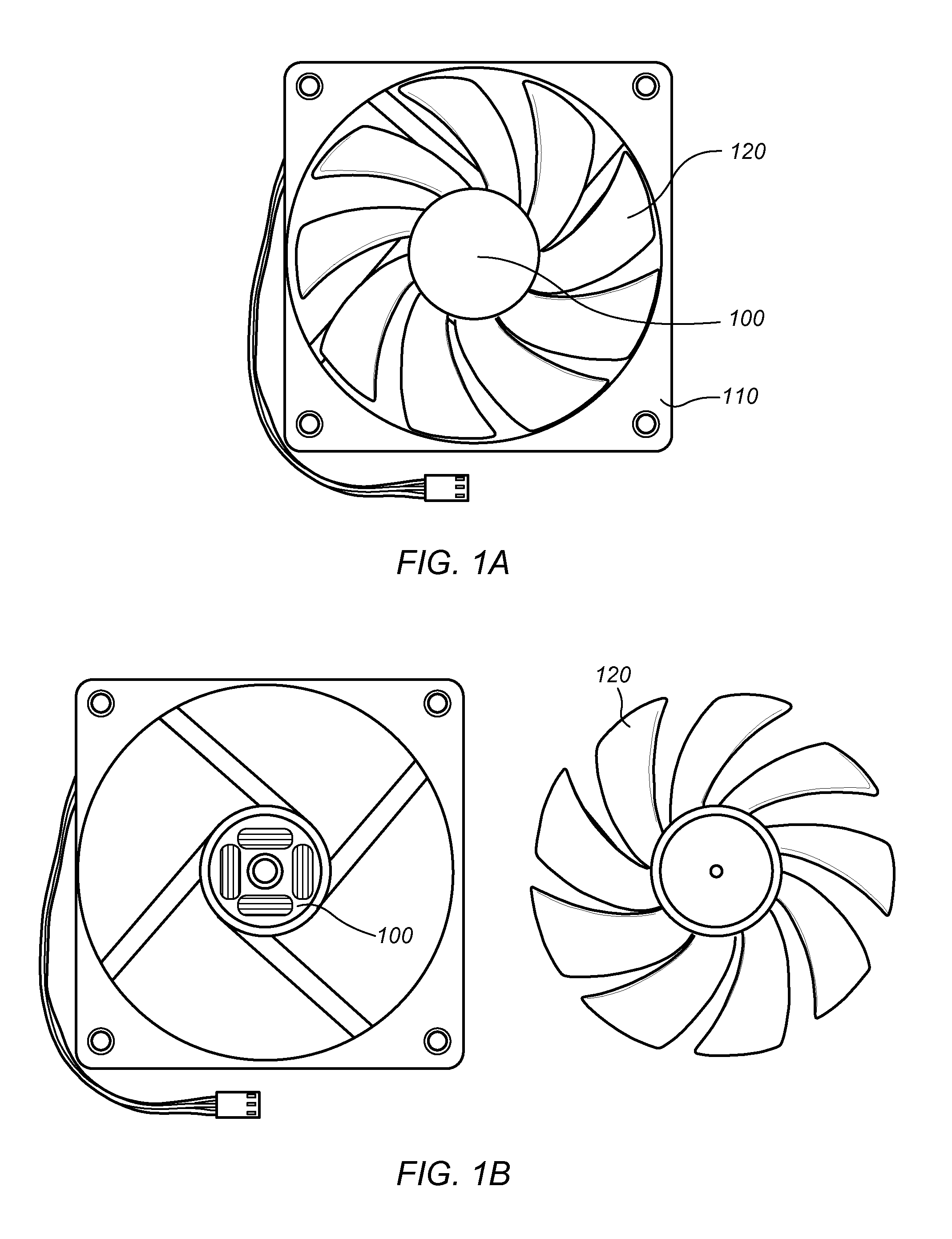
[0027]FIGS. 1A and 1B illustrate an exemplary fan assembly 110 according to one embodiment. Fan 110 may be a cooling fan, for example a fan for use in a laptop or a desktop computer. Fan 110 may alternatively be a commercial or industrial fan, or in general any type of fan driven by a motor. Fan assembly 110 may include a motor assembly 100 as well as fan blades 120. Motor assembly 100 may comprise a motor (e.g. motor 102 shown in FIG. 5) as well as drive circuitry (for example, drive control logic 502 shown in FIG. 5) for controlling motor 102.

[0028]Although FIGS. 1A and 1B illustrate a fan as the load being driven by the motor, it should be noted that the system and method for controlling a motor as described herein may be suited for driving any of various types of loads, including without limitation hard disk drives, drive motors for appliances, propellers, wheels, pumps, or other loads.

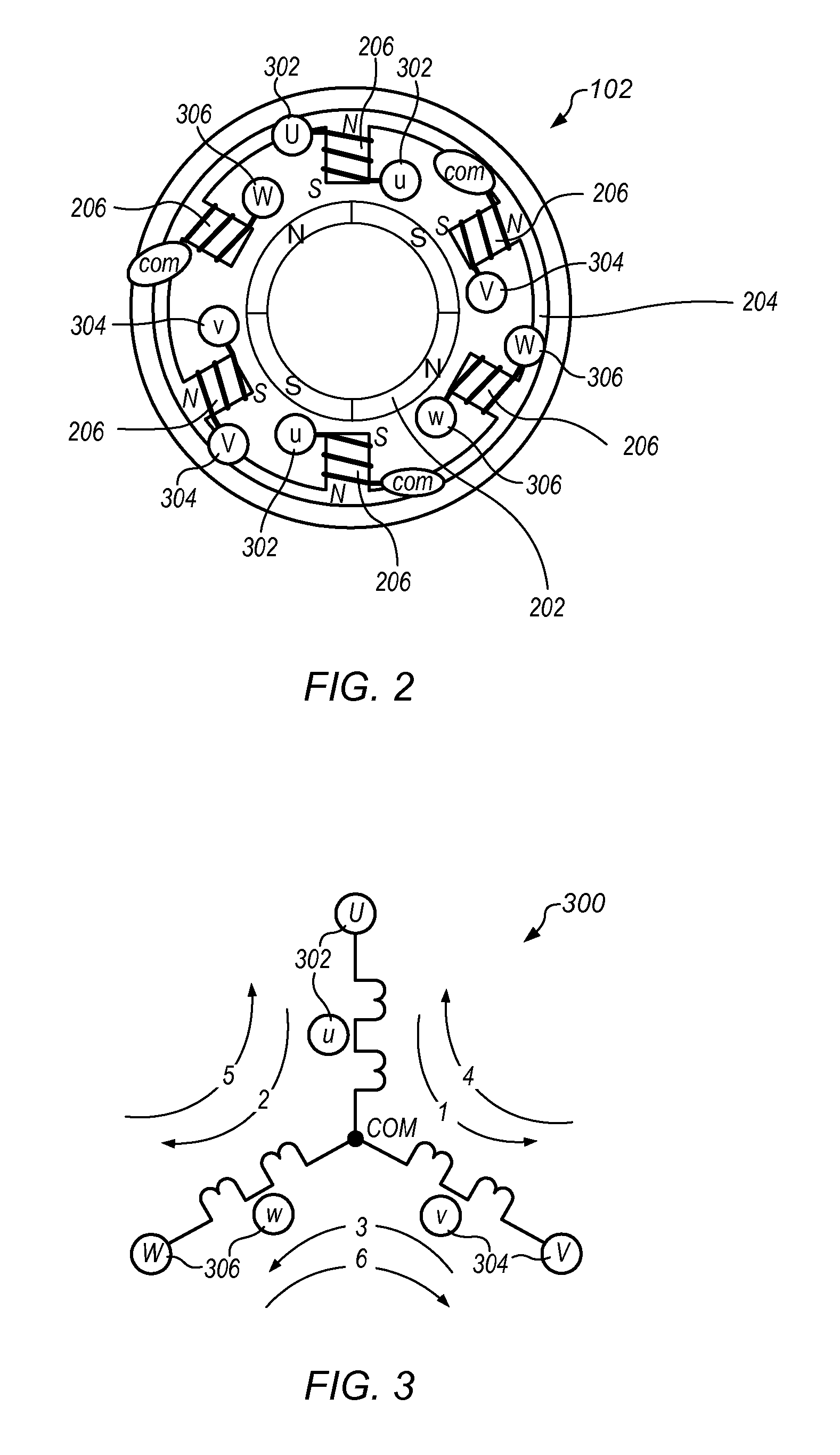
FIG. 2—Brushless Four-Pole Three-Phase Motor

[0029]F...


PUM


Abstract

A control method for a sensor-less, brushless, three-phase DC motor. The stator coil in the electromagnets inside the motor may be used as the inductive element through which a voltage regulator can regulate the current as a means of regulating the output voltage. The value of the control signal provided to the drivers controlling power to the coils may be calculated based on at least the rail voltage, as measured in real time. This allows for a wide variation of input voltages, while maintaining a relatively constant output power to the motor. In general, by taking into account the value of the rail voltage when determining the final value of the control signal that is applied to the stator coils, the maximum current through the stator coils may be scaled to the same magnitude current that would be expected to flow through the coils if the rail voltage were the rated (nominal) fan / motor voltage, even when the actual rail voltage is different, e.g. higher than the rated fan / motor voltage.

Description

INCORPORATION BY REFERENCE[0001]U.S. patent application Ser. No. 12 / 393,996, titled “Brushless, Three Phase Motor Drive”, filed Feb. 26, 2009 and whose inventors are Lynn R. Kern and James P. McFarland; U.S. provisional application Ser. No. 61 / 108,320 titled “Sensor-less, Brushless, Three Phase Motor Drive”, filed on Oct. 24, 2008 and whose inventor is Lynn R. Kern; U.S. patent application Ser. No. 12 / 620,726, titled “Brushless, Three Phase Motor Drive”, filed Nov. 18, 2009 and whose inventors are Lynn R. Kern, Scott C. McLeod, and Kenneth W. Gay; and U.S. patent application Ser. No. 12 / 632,495, titled “Drive Method to Minimize Vibration and Acoustics In Three Phase Brushless DC (TPDC) Motors”, filed Dec. 7, 2009 and whose inventors are Lynn R. Kern and James P. McFarland are all hereby incorporated by reference in their entirety as though fully and completely set forth herein.BACKGROUND OF THE INVENTION[0002]1. Field of the Invention[0003]The invention generally relates to DC (Dire...

Claims


Application Information

Patent Timeline
Patent Type & Authority Patents(United States)
IPC IPC(8): H02P6/00
CPCH02P6/182H02P7/0044H02P7/04
Inventor KERN, LYNN, R.
Owner MICROCHIP TECH INC
Why Eureka
Try Eureka