Snaring systems and methods

a technology of pacing leads and snares, which is applied in the field of snares grasping pacing leads, can solve the problems of pig tail catheters having limited holding capacity, snares grasping the lead with inappropriate levels of force, and may not be well suited for easy accessing, grasping or manipulating the free end

Active Publication Date: 2015-12-29
SPECTRANETICS
View PDF23 Cites 17 Cited by
  • Summary
  • Abstract
  • Description
  • Claims
  • Application Information

AI Technical Summary

Benefits of technology

[0008]Grasping snares and method for grasping a pacing lead and removing it from the body are disclosed herein. For example, an operator may advance a snaring system through a jugular access site in a patient, providing a relatively non-tortuous pathway to the superior vena cava where the snaring system can be engaged with a pacing lead. Using the snaring system, it is possible to maneuver the pacing lead, which optionally may involve pulling the lead so as to disengage a proximal portion or a distal portion of the lead from an attachment site within the patient. Once a distal or proximal portion of the pacing lead is disengaged, the physician can maneuver the free end toward the access site, by loosely engaging the snaring system with the pacing lead. In some cases, this may involve the use of a snaring system having one or more roller bearings or sleeves. The snaring system can be translated along a length of the pacing lead, and can be used to maneuver or pull a free end of the pacing lead, without transmitting an excessive amount of pulling force or stress on the opposing secured end of the pacing lead.
[0010]Relatedly, embodiments of the present invention encompass systems and methods for snaring or grasping a lead which is disposed within an anatomical location of the patient, such as the jugular vein, the superior vena cava, the right atrium, the right ventricle, the brachiocephalic vein, or the like. Advantageously, the techniques disclosed herein allow a surgeon or operator to effectively grasp, push, pull, twist, rotate, or otherwise maneuver or manipulate an object, such as a pacing lead, within the patient. What is more, snaring systems disclosed herein can withstand high pulling forces without releasing a pacing lead, and can effectively snare a lead in a midsection or central portion, without being threaded over the end of the pacing lead. Exemplary snaring systems allow a pacing lead to slide through a distal hook of a snare wire, without imparting high forces to the pacing lead or adhered vasculature. Features such as a hook tag end and a bent or shaped snare wire allow an operator to effectively steer or navigate the snare system to the pacing lead for capture. Moreover, snaring systems disclosed herein are easily releasable from the pacing lead. In some cases, snaring systems can include a hook or snare that can hook and retain a pacing lead, and pull a portion of the pacing lead downward toward the femoral vein or upward toward the jugular vein and out of the access site. Systems can also allow the pacing lead to move through a snare wire or catch mechanism as the lead is being pulled or during the snaring process. Exemplary embodiments can also release a hook or snare if the procedure is not successful or is interrupted.

Problems solved by technology

However, some approaches may not be well suited for easily accessing, grasping, or manipulating the free end of a lead.
For example, some pig tail catheters may have a limited holding capability, and the lead may slip out of the catheter before it is freed from the patient's anatomy.
Some snares grasp the lead with inappropriate levels of force.

Method used


Image

  • Snaring systems and methods
  • Snaring systems and methods
  • Snaring systems and methods

Examples


Embodiment Construction

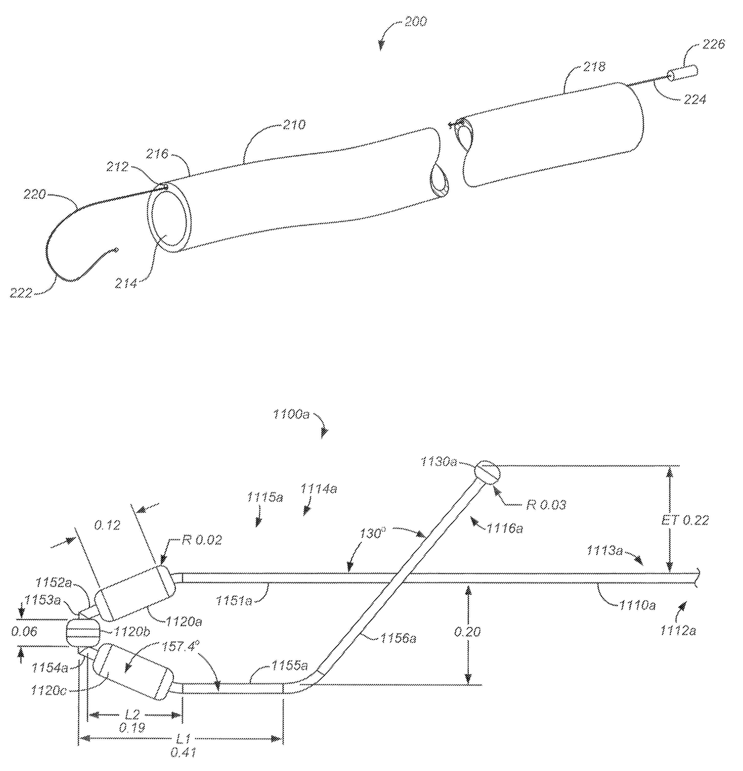
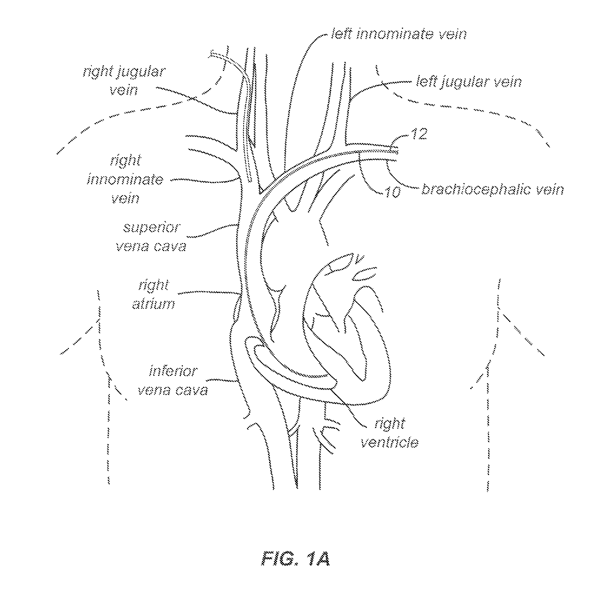
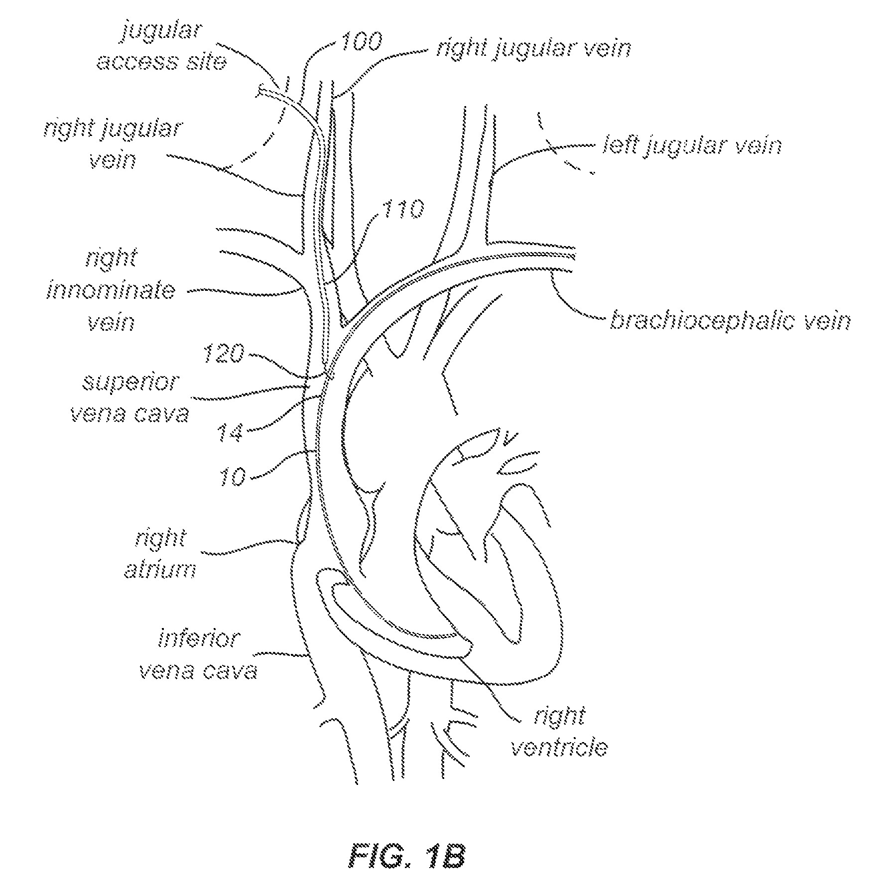
[0031]In certain surgical situations, a patient may present with a pacing lead that is no longer disposed within the pocket, but instead is freely floating in the brachiocephalic vein, the superior vena cava, the right atrium, or the like. Embodiments of the present invention provide techniques for grasping a free end of the pacing lead and maneuvering or pulling it toward the jugular vein. Exemplary approaches provide removal or snare systems that can hook, grasp, push, pull, and twist a pacing lead. Such advances allow an operator may degrees of freedom when removing a lead having a free end.

[0032]According to embodiments of the present invention, techniques may include pulling the free end of the lead down from the femoral vein using a femoral vein approach. Once the lead is located within the right atrium or inferior vena cava, the physician can use a snare device inserted through the jugular vein to grasp or engage the lead and pull it toward an opening or incision in the jugul...


PUM


Abstract

Snaring systems and methods involve engaging objects such as pacemaker pacing leads within a patient. Physicians can use snaring systems having loops, tags, and roller mechanisms to remove a pacing leads from a patient. For example, snaring systems can be inserted through a jugular access site, engaged with a pacemaker pacing lead, and withdrawn through the jugular access site so as to remove a portion of the pacing lead. Lead extraction techniques can be employed to further dislodge the pacing lead from the patient.

Description

CROSS-REFERENCES TO RELATED APPLICATIONS[0001]This application is a nonprovisional of and claims the benefit of priority to U.S. Provisional Patent Application No. 61 / 242,225 filed Sep. 14, 2009, the contents of which are incorporated herein by reference for all purposes.BACKGROUND OF THE INVENTION[0002]Embodiments of the present application relate generally to systems and methods for separating or removing an object from a patient, and more specifically, to techniques for grasping pacing leads within a patient.[0003]A pacemaker can be used to improve heart function in a patient. For example, a pacemaker can transmit electrical signals to the patient's heart, so as to assist the heart to beat in a desired heart rhythm. A pacing system typically includes a pacemaker, a pacing lead, and a controller or processor. A pacing lead often has a wire that transmits electrical impulses to cardiac tissue. Optionally, a pacing lead may transmit information regarding cardiac activity to the pace...

Claims


Application Information

Patent Timeline
Patent Type & Authority Patents(United States)
IPC IPC(8): A61B17/24A61B17/26A61B17/221A61B17/34A61N1/05
CPCA61B17/221A61B17/3468A61N2001/0578A61B2017/2217
Inventor TAYLOR, KEVIN D.BURTON, PETEATWELL, DAVEBOWE, WADE
Owner SPECTRANETICS
Why Eureka
Try Eureka