Hinged metal connectors and joint constructions

a technology of metal connectors and joints, applied in the direction of construction, covering/lining, building construction, etc., can solve the problems of high cost of contactors, insufficient ageing or even being left, and large amount of lumber

Active Publication Date: 2015-12-29
CLARKWESTERN DIETRICH BUILDING SYST
View PDF29 Cites 7 Cited by
  • Summary
  • Abstract
  • Description
  • Claims
  • Application Information

AI Technical Summary

Benefits of technology

[0011]Still another advantage of the present invention is that it can be used to form a straight joint for the drywall even with uneven or inconsistent framing because the tabs by which the wings are affixed to the rafters can be bent to straighten the so that the joint where the drywall ends meet is straight.
[0012]These and other objects and advantages will become apparent hereinafter.
[0013]The invention resides in a novel metallic connector and drywall ceiling construction in which the connector of this invention is positioned adjacent to the ceiling rafters between the underside of the ceiling drywall and the ceiling rafters beneath the ridge board. The connector allows movement of the rafters while maintaining the wallboard, and the wallboard outer finish tape and drywall compound, in their fixed position to resist cracking of the taped joint between the wallboard sections where they join beneath the ridge board.
[0014]In the drawings, wherein like numbers and letters refer to like parts wherever they occur:
[0015]FIG. 1 is a fragmentary perspective view of a ceiling and ridge construction showing wallboard installed over one modification of the connector of this invention, but not showing the finish tape and drywall compound;
[0016]FIG. 2 is a plan view of the one form of the connector of this invention;

Problems solved by technology

Much lumber is not aged adequately or even can be left uncovered on a job site so that it has more moisture than is desirable.
When the lumber is installed in a moisture laden condition, it tends to shrink and warp when it dries out.
This is very expensive to the contactor, both in time and money and in loss of reputation for building a quality house.
Since many houses using this type construction are custom built and very expensive, this is important to the contractor.
This is important during installation in cold weather months, because the drywall mud applied to the interior drywall joint does not cure properly under cold or freezing conditions.

Method used


Image

  • Hinged metal connectors and joint constructions
  • Hinged metal connectors and joint constructions
  • Hinged metal connectors and joint constructions

Examples


Embodiment Construction

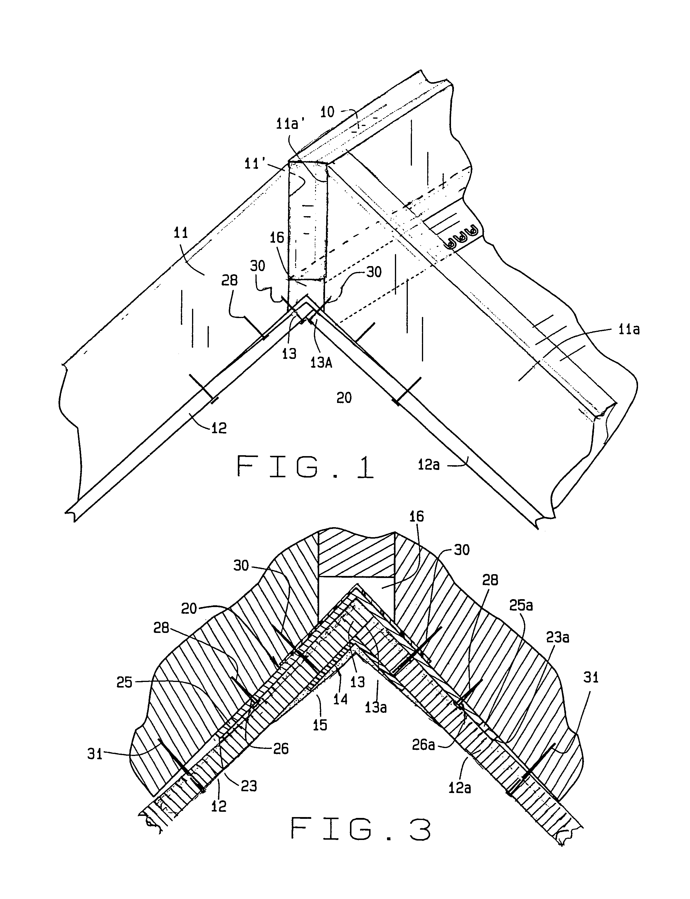
[0027]FIG. 1 shows a typical vaulted ceiling room structure which includes a ridge board 10 and inclined ceiling rafters 11,11a which butt against the ridge board 10 and are fastened thereto. Since the rafters 11,11a are cut on an angle, the cut edges 11′, 11a′ are longer than the width of the ridge board 10 which leaves a space 16 beneath the ridge board 10. Fastened to the ceiling rafters 11,11a in a conventional structure are drywall boards 12,12a whose inner ends 13,13a abut beneath the ridge board 10 in the space 16. Conventional drywall tape 14 (FIG. 3) is positioned over the joint between the abutting edges 13,13a, and the tape 14 is covered by drywall compound 15 which is finished smooth by the taper. The drywall tape 14 can be of various conventional types but a preferred form of the tape 14 is covered by U.S. Pat. Nos. 5,418,027 and 5,037,686 owned by the inventor of this application and sold under the trademark STRAIT-FLEX® by Strait-Flex International, Inc. of St. Louis,...


PUM


Abstract

A method of preventing disruption of a taped finished drywall board joint in a room having a center ridge member and angularly inclined ceiling rafters which involves a metallic connector positioned between the wallboard sections and the ridge member and rafters. The connector has two metallic wings with a center longitudinal bendable connection. The wings have flexible tabs at their free edges which are attached to the rafters and the connector itself is attached to the wallboard adjacent to the ridge member. The wallboard also is attached to the rafters 8-12 inches from the edges of the wings. Because the tabs can bend away from the wings, this construction allows the joint to flex if the rafters warp or shrink without disrupting the finish coating on the outside of the wallboard joint at the ridge member. The connector also can be applied to other critical joints in a home where the framing members are subject to movement such as flat ceilings to avoid truss uplift or rafter movement. The wings have longitudinal corrugations in the wings and tabs to strengthen the tape. In one embodiment two wings are connected by a polymeric tape. In another embodiment, the connector is a unitary metallic part with a longitudinal line of perforations connecting the wings along the centerline to allow the connector to be bent to form the two diverging wings.

Description

CROSS-REFERENCE TO RELATED APPLICATIONS[0001]This application is related to my Provisional application Ser. No. 60 / 458,630 filed Mar. 28, 2003 entitled Hinged Drywall Tape and Joint Construction and my Provisional application Ser. No. 60 / 468,849 filed May 6, 2003 entitled Hinged Metal Connector and claims priority from said applications.STATEMENT REGARDING FEDERALLY SPONSORED RESEARCH OR DEVELOPMENT[0002]Not Applicable.FIELD OF THE INVENTION[0003]This invention relates to a metal connector construction designed to be positioned between roof rafters and a drywall ceiling and along room corner joints and in bay windows. In one embodiment, the connector is a composite having metallic wings and a plastic hinge. This invention also relates to a metallic connector that has perforations along the hinge line to form two wings and the wings have bendable metal tabs which can be connected to ceiling rafters to allow for movement in the structural members without a break in the taped finish dr...

Claims


Application Information

Patent Timeline
Patent Type & Authority Patents(United States)
IPC IPC(8): E04B1/38E04F13/06
CPCE04F13/06E04F2013/063
Inventor CONBOY, JOHN S.
Owner CLARKWESTERN DIETRICH BUILDING SYST
Why Eureka
Try Eureka