
Flexible barrier composite fabrics via an adhered film process

a technology of adhesion film and flexible barrier, which is applied in weaving, pedestrian/occupant safety arrangements, vehicular safety arrangements, etc., can solve the problems of severe limits on the maximum thickness attainable, two coating stations pose a difficult challenge, and it is nearly impossible to guarantee substantially leakproof quality

Active Publication Date: 2015-12-29
DARTEX COATINGS INC
View PDF2 Cites 12 Cited by
  • Summary
  • Abstract
  • Description
  • Claims
  • Application Information

AI Technical Summary

Benefits of technology

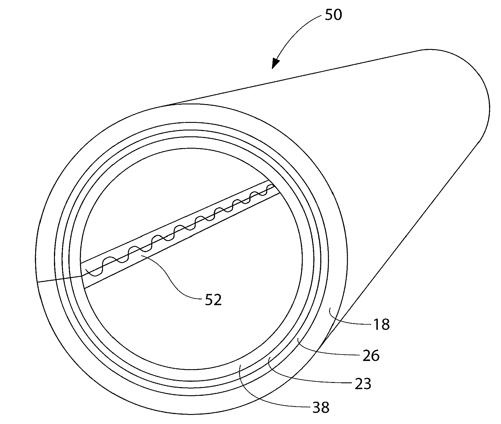
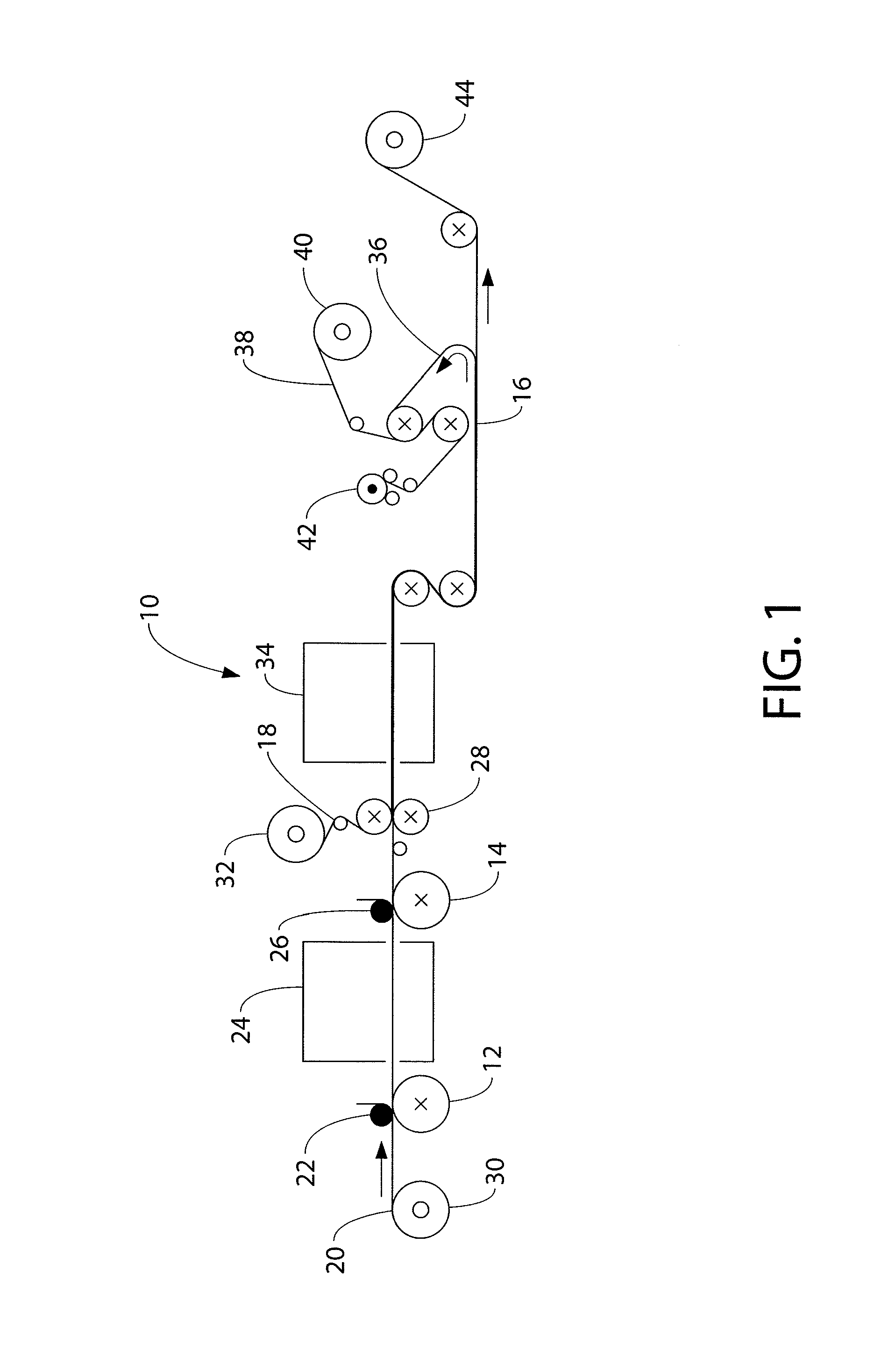
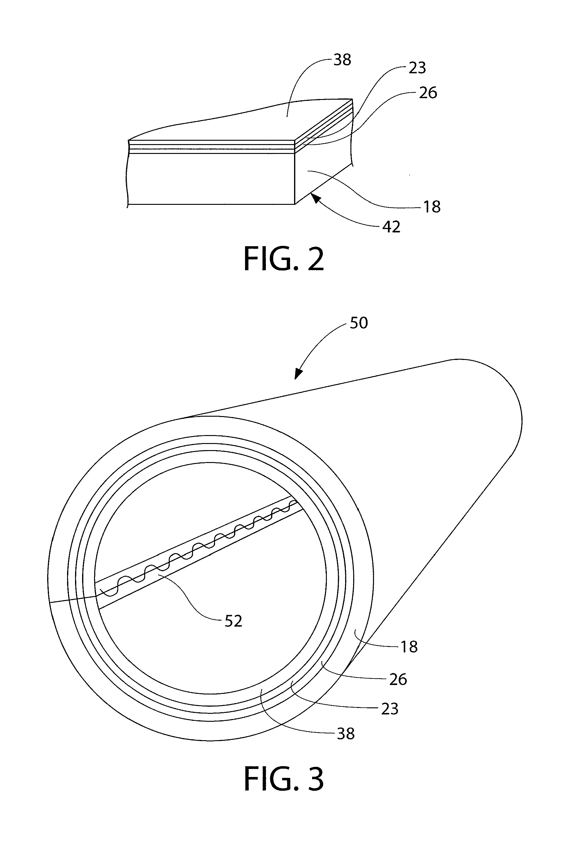
The invention is a composite fabric that is resistant to high hydrostatic pressure and is flexible enough to be formed into a tube and everted. The fabric is made up of a fabric backing, an adhesive layer, a midlayer barrier, and an external barrier. The adhesive layer is made of a polyurethane composition and the midlayer barrier is made of an aromatic polyether polyurethane composition. The external barrier can be a pre-formed polymeric film, such as an extruded thermoplastic polyurethane film, a polyester film, a natural or synthetic rubber film, a polyamide film, or a polyolefin film. The composite fabric can be used as a liner for cured-in-place-pipe repair and has good hydrostatic pressure resistance. The process for producing the composite fabric involves applying a midlayer barrier coating solution to a release layer, then an adhesive to the midlayer barrier, and finally an external barrier to the midlayer barrier. The composite fabric can be formed into a tubular liner for cured-in-place-pipe repair.

Problems solved by technology

Achieving this goal on a transfer coating line having only two coating stations poses a difficult challenge.
In fact, since the “barrier” layer would have to be cast from solution at the first, single coating head, there would be severe limits imposed on the maximum thickness attainable, not to mention that it would be nearly impossible to guarantee substantially leakproof quality when depending upon just one layer.

Method used


Image

  • Flexible barrier composite fabrics via an adhered film process
  • Flexible barrier composite fabrics via an adhered film process
  • Flexible barrier composite fabrics via an adhered film process

Examples


example 1

[0082]Composite fabrics, based on a high pile sliver knit useful for the cured-in-place lining of gravity and pressure pipes including potable water pipes, were produced using the apparatus and process shown in FIG. 1. Tables 2 and 3, which follow, specify the materials and process variables used.

[0083]

TABLE 2MaterialsMaterialDescriptionProduct CodeSupplierRelease2 mil Silicone-Coated2MIL PET C / 1 / SMPI Release LLCCarrierPolyester Release LinerEASY RELEASEMidlayerSolution Compound ofEAF535-1Dartex Coatings Inc.BarrierAromatic PolyetherCoatingPolyurethaneSolutionLiquidAqueous Compound ofEAF525-16Dartex Coatings Inc.AdhesiveAliphatic Polyurethanewith PolyisocyanateCurativeFabricPolyester High Pile SliverFPL0007330011.25020HS0Draper MillsBackingKnitBarrier Film2 mil Aromatic137 Matte × 0.002″Tuftane ETIPolycarbonatePolyurethaneFilm

[0084]

TABLE 3Process VariablesProcessVariableControlled VariableValueNotesMidlayerApplied (dry) weight, oz / yd20.65ThicknessDryingTemperature, ° F. / Dwell, s200 / ...

example 2

[0087]Another high pile based composite fabric employing a thicker barrier layer useful for the cured-in-place lining of gravity and pressure-pipes, was produced using the apparatus and process shown in FIG. 1. Tables 5 and 6, which follow, specify the materials and process variables used.

[0088]

TABLE 5MaterialsMaterialDescriptionProduct CodeSupplierRelease Carrier2 mil Silicone-Coated2MIL PET C / 1 / SMPI Release LLCPolyester Release LinerEASY RELEASEMidlayer BarrierSolution Compound ofEAF535-1Dartex Coatings Inc.Coating SolutionAromatic PolyetherPolyurethaneLiquid AdhesiveAqueous Compound ofEAF525-18Dartex Coatings Inc.Aliphatic PolyurethanewithPolyisocyanate CurativeFabric BackingHigh Pile Sliver Knit733 / 0011Draper KnittingBarrier Film6 mil Aromatic137 Matte × 0.006″Tuftane ETIPolycarbonatePolyurethane Film

[0089]

TABLE 6Process VariablesProcess VariableControlled VariableValueNotesMidlayer ThicknessApplied (dry) weight, oz / yd20.65Drying (Dryer #1)Temperature, ° F. / Dwell, s200 / 180Liquid...

example 3

[0092]Lower thickness, fleece-backed composite fabrics useful for the cured-in-place lining of gravity and pressure-pipes, were produced using the apparatus and process shown in FIG. 1. Tables 8 and 9, which follow, specify the materials and process variables used.

[0093]

TABLE 8MaterialsMaterialDescriptionProduct CodeSupplierRelease Carrier2 mil Silicone-Coated2MIL PET C / 1 / SMPI Release LLCPolyester Release LinerEASY RELEASEMidlayer BarrierSolution Compound ofEAF535-1Dartex Coatings Inc.Coating SolutionAromatic PolyetherPolyurethaneLiquidAqueous Compound ofEAF525-18Dartex Coatings Inc.AdhesiveAliphatic Polyurethane withPolyisocyanate CurativeFabric BackingPolyester Fleece9534Polartec LLCBarrier Film6 mil Aromatic Polycarbonate137 Matte × 0.006″Tuftane ETIPolyurethane Film

[0094]

TABLE 9Process VariablesProcess VariableControlled VariableValueNotesMidlayer ThicknessApplied (dry) weight, oz / yd20.65Drying (Dryer #1)Temperature, ° F. / Dwell, s200 / 180Liquid AdhesiveApplied (dry) weight, oz / yd...


PUM

PropertyMeasurementUnit
temperatureaaaaaaaaaa

Abstract

A composite fabric includes: a fabric backing; an adhesive layer; a midlayer barrier bonded to the fabric backing by the adhesive layer; and an external barrier bonded to the midlayer barrier, wherein the composite fabric has a hydrostatic pressure resistance of at least 100 psi and is sufficiently flexible such that it can be formed into a tube and everted. A process and an apparatus for producing the composite fabric are also disclosed. The composite fabric is particularly suitable for use as a liner in a cured-in-place pipe repair method.

Description

BACKGROUND OF THE INVENTION[0001]1. Field of Invention[0002]This invention relates to the manufacture of flexible coated fabrics with high barrier properties.[0003]2. Description of Related Art[0004]The attachment of polymeric coatings to flexible webs (e.g. fabrics) to provide a flexible composite with barrier properties, for example waterproofness, is well known. Existing methods typically employed to produce such composites from flexible webs include the lamination of pre-formed films (laminating), such as taught in, e.g., U.S. Pat. Nos. 5,709,766 and 5,902,753; the direct application of liquid coating compositions followed by drying and / or curing (direct coating), such as taught in, e.g., U.S. Pat. Nos. 5,902,753 and 6,734,123; and the application of liquid coating compositions to a temporary carrier having release properties, followed by drying and / or curing before being transferred from the carrier and adhered to the substrate web (transfer coating), such as taught in, e.g., U...

Claims


Application Information

Patent Timeline
Patent Type & Authority Patents(United States)
IPC IPC(8): B29C73/00B32B37/00B29D22/00B29D23/00B32B1/08B60R21/16B32B27/08F16L11/04B32B7/12B32B27/12F16L55/18B32B5/02B32B25/10B32B27/34B32B27/36B32B27/40F16L55/165B29C65/00B32B43/00
CPCB32B27/40B32B27/36B32B43/00F16L55/1656F16L55/18B32B1/08B32B5/02B32B5/022B32B5/024B32B5/026B32B7/12B32B25/10B32B27/12B32B27/34B32B37/025B32B2255/02B32B2255/26B32B2274/00B32B2307/50B32B2597/00Y10T156/15Y10T428/1362Y10T442/3862Y10T442/40Y10T442/675
Inventor COLASANTO, THOMAS C.
Owner DARTEX COATINGS INC
Learn More