Micro-inverter quick mount and trunk cable

Inactive Publication Date: 2015-12-29
CONCISE DESIGN
View PDF7 Cites 21 Cited by
  • Summary
  • Abstract
  • Description
  • Claims
  • Application Information

AI Technical Summary

Benefits of technology

[0018]A single AC trunk cable electrically connects all of the micro-inverter modules in the system or string. The AC trunk cable may be a flat cable with conductors. Each micro-inverter includes a flat jumper output cable with a corresponding number of conductors as the AC trunk cable. When a micro-inverter is installed, the jumper output cable is easily connected into the AC trunk cable.
[0019]In one embodiment, the flat jumper output cable has a distal end, where the distal end is enclosed in a molded housing. Piercing elements are formed within the molded housing. One set extends inwardly of the molded housing to electrically engage the jumper cable conductor

Problems solved by technology

This adds a level of cost, complexity and associated installation labor.
There are also inherent dangers.
DC strings from solar panels can exceed 600 volts, which cannot be readily shut off.
Although there are obvious advantages in employing micro-converters for the conversion of DC to AC emanating from solar panels, such products have experienced issues limiting t

Method used


Image

  • Micro-inverter quick mount and trunk cable
  • Micro-inverter quick mount and trunk cable
  • Micro-inverter quick mount and trunk cable

Examples


Example

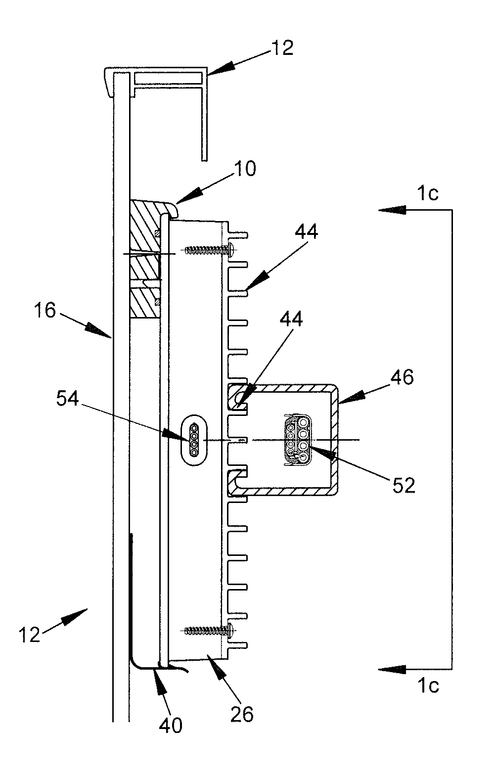
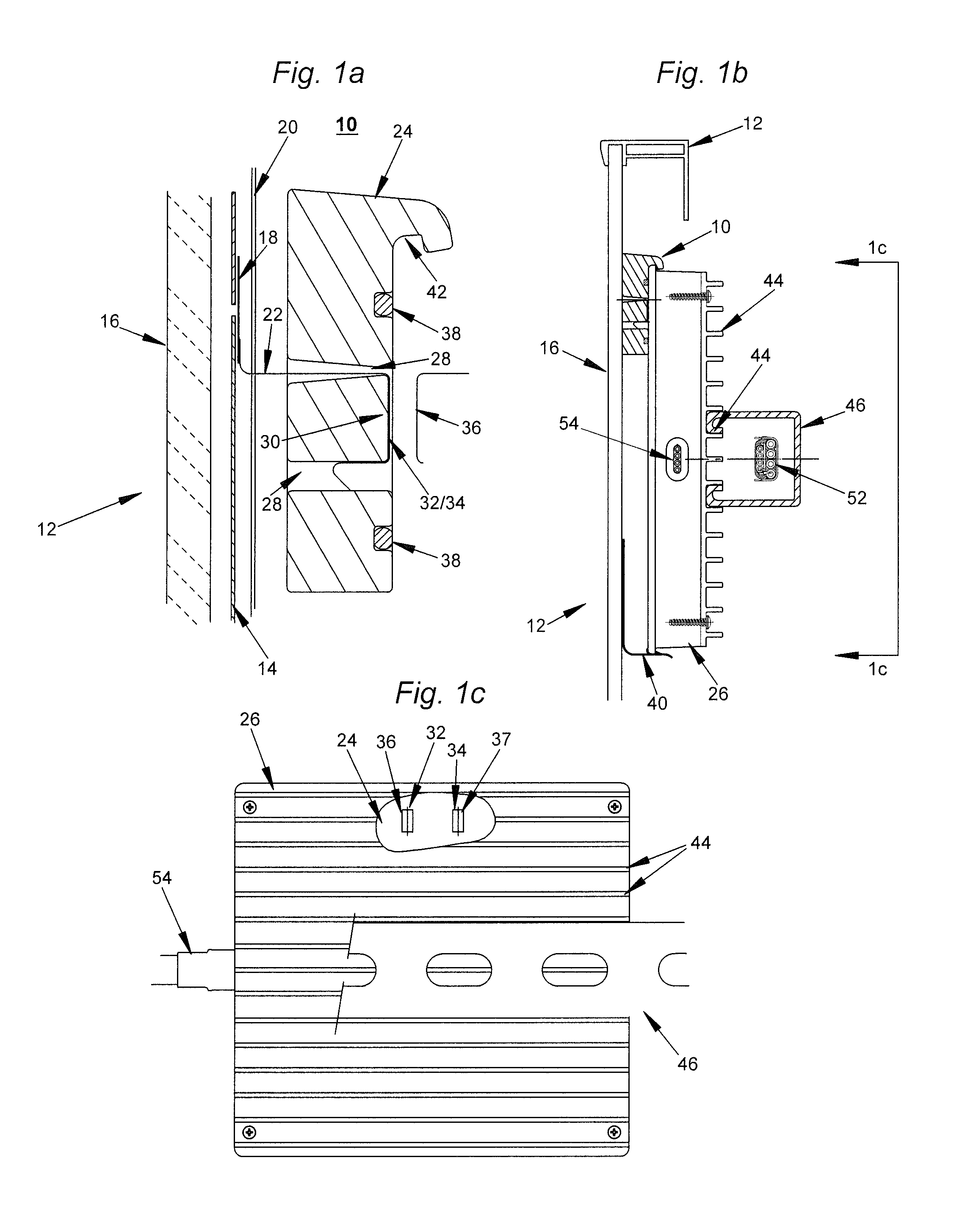
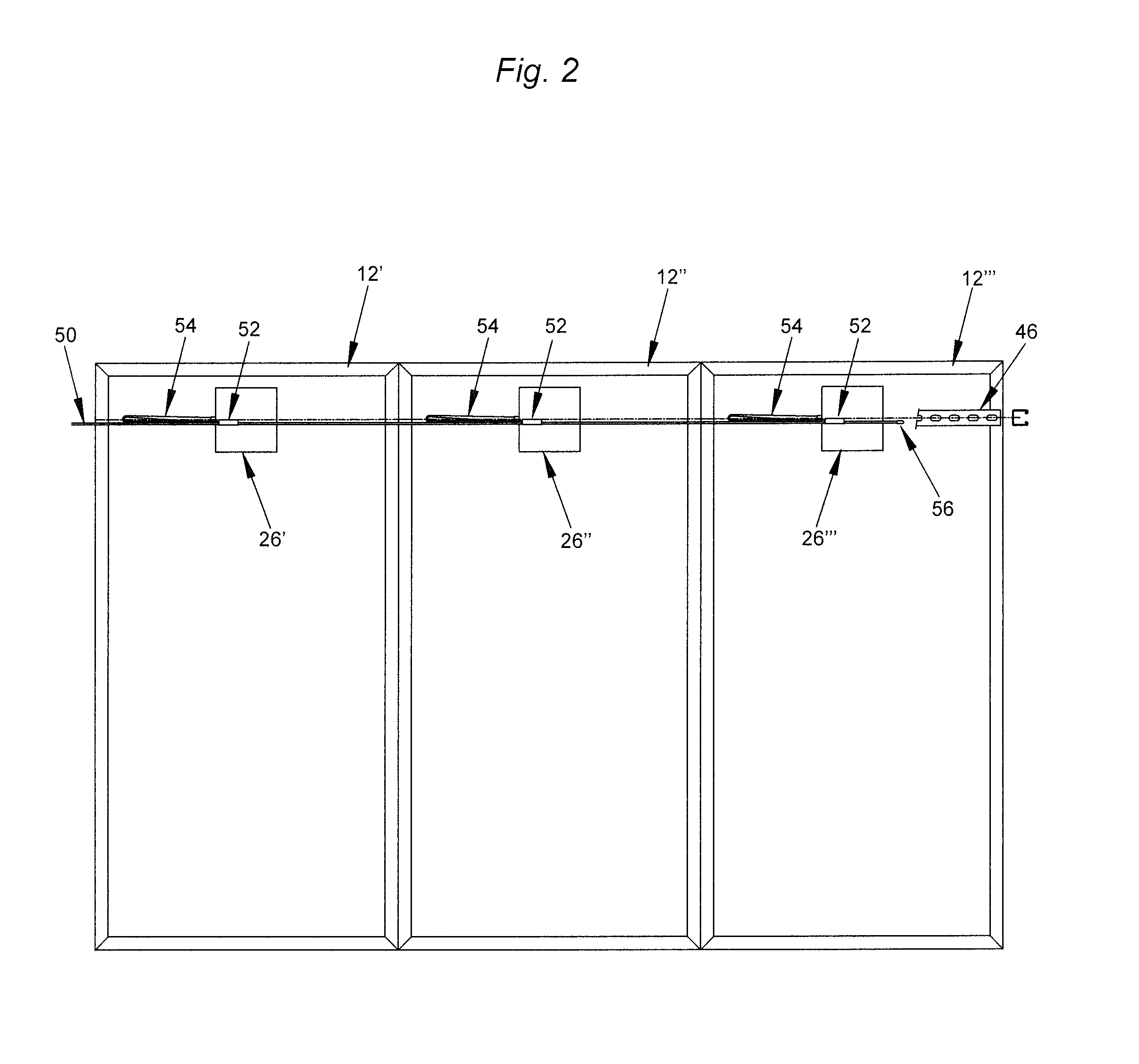
[0032]Novel features which are characteristic of the invention, as to organization and method of operation, together with further objects and advantages thereof will be better understood from the following description considered in connection with the accompanying drawings, in which preferred embodiments of the invention are illustrated by way of example. It is to be expressly understood, however, that the drawings are for illustration description only and are not intended as definitions of the limits of the invention. The various features of novelty which characterize the invention are recited with particularity in the claims.

[0033]There has been broadly outlined more important features of the invention in the summary above and in order that the detailed description which follows may be better understood, and in order that the present contribution to the art may be appreciated. There are, of course, additional features of the invention that will be described hereinafter and which w...


PUM


Abstract

A photovoltaic system is disclosed having individual micro-inverters associated with each solar panel. The individual micro-inverters are easily installed without the aid of tools by snap locking a micro-inverter into place upon heat barriers mounted to and separated from the solar panels. When a micro-inverter is snapped into place it automatically electrically engages contacts from the solar panels mounted on the heat barriers. AC trunk cables pass through uni-strut channels along the backs of the solar panels. Flat jumper output cables from the micro-inverters fit adjacent the AC trunk cables within the uni-strut channels where a snap fit electrical connection is made, in a protected environment.

Description

RELATED APPLICATION DATA[0001]The present application claims priority of U.S. Provisional Patent Application Ser. No. 61 / 769,077 filed Feb. 25, 2013.TECHNICAL FIELD[0002]The present invention is directed to photovoltaic solar panels or modules which may be mounted on rooftops, racks or other places where sunlight is available to convert sunlight to electrical power. The output from photovoltaic solar panels is a DC voltage. Inverters convert the DC voltage to AC voltage. The present invention is directed to photovoltaic solar panels where each solar panel is provided with its own micro-inverter.BACKGROUND OF THE INVENTION[0003]Solar panels produce direct current (DC) which must be converted to alternating current (AC). Typically, useable outputs from solar panel installations are 240 volts AC at 60 Hz for North American installations. In some photovoltaic solar panel installations a single inverter may convert the DC outputs to AC from a string of solar panels.[0004]Using a single i...

Claims


Application Information

Patent Timeline
IPC IPC(8): H02S40/32H02J3/00H02J3/38H02M7/00H02M1/00
CPCH02M1/00H02J3/00H02S40/32H02J3/383H02M7/003Y02E10/56
Inventor TWEEDIE, RICHARD
Owner CONCISE DESIGN
Why Eureka
Try Eureka