Thin plate-reinforcement structure utilizing reinforcing effect of weld bead and method of producing the same

a technology of reinforced structure and weld bead, which is applied in the direction of manufacturing tools, movable seats, transportation and packaging, etc., can solve problems such as fatigue cracks

Active Publication Date: 2016-01-05
DELTA KOGYO CO LTD
View PDF24 Cites 6 Cited by
  • Summary
  • Abstract
  • Description
  • Claims
  • Application Information

AI Technical Summary

Benefits of technology

[0012]However, in an operation of welding a component (e.g., lower frame (reinforcing member)) to a thin plate component (e.g., side frame) having a thickness of about 0.5 mm, it is often the case that they are spot-welded discontinuously at about several positions. In this situation, stress concentration does not occur in all of the resulting discontinuous weld areas, but it is more likely to occur in specific one or more of the weld areas, causing fatigue crack. Thus, it is effective to determine in which of the weld areas stress concentration occurs, and apply, to the determined weld area, a countermeasure for suppressing the occurrence of fatigue crack.
[0013]For this purpose, it is effective to employ arc-welding having high flexibility in setting of weld position and length, instead of employing spot-welding having restrictions on weld position and length and difficulty in setting of stress dispersion.
[0014]The present invention has been made based on the above findings, and an object thereof is to provide a thin plate-reinforcement structure utilizing a reinforcing effect of a weld bead, which is capable of effectively achieving prevention of the occurrence of fatigue crack in a thin plate component, or delay in an occurrence timing of the fatigue crack, almost without causing an increase in cost and weight, and a method of producing the thin plate-reinforcement structure.
[0015]In order to solve the above object, according to one aspect of the present invention, there is provided a method of producing a thin plate-reinforcement structure utilizing a reinforcing effect of a weld bead. The method comprises: a first step of preparing a first component including a thin plate portion, and a second component having a thickness greater than that of the thin plate portion; and a second step of welding the first component and the second component together. The second step includes the sub-steps of: welding the first component and the second component together through at least one weld area; and providing a stress-dispersing weld bead to extend from an overlapping region between the weld area and the first component, onto the first component or the second component, wherein the stress-dispersing weld bead is set to a direction and length capable of preventing fatigue crack from occurring in the first component.
[0016]In the present invention, during an operation of welding a thin plate component (hereinafter referred to also as “first component”) and another component (hereinafter also referred to as “second component”), the stress-dispersing weld bead is provided to extend from an overlapping region between a weld area, subject to stress concentration and the thin plate component (first component), onto the first or second component. This makes it possible to effectively achieve prevention of the occurrence of fatigue crack in the thin plate component, or delay in an occurrence timing of the fatigue crack.
[0017]In addition, the stress-dispersing weld bead can be laid, following the operation process of welding, to the thin plate component (first component), another component (second component). Thus, the operation process of laying the stress-dispersing weld bead falls within the range of a usual welding operation process and requires no special technique, so that there is almost no increase in cost. Furthermore, it is only necessary to simply lay the stress-dispersing weld bead, so that there is almost no increase in weight of a welded structure.

Problems solved by technology

In this situation, stress concentration does not occur in all of the resulting discontinuous weld areas, but it is more likely to occur in specific one or more of the weld areas, causing fatigue crack.

Method used


Image

  • Thin plate-reinforcement structure utilizing reinforcing effect of weld bead and method of producing the same
  • Thin plate-reinforcement structure utilizing reinforcing effect of weld bead and method of producing the same
  • Thin plate-reinforcement structure utilizing reinforcing effect of weld bead and method of producing the same

Examples


first embodiment

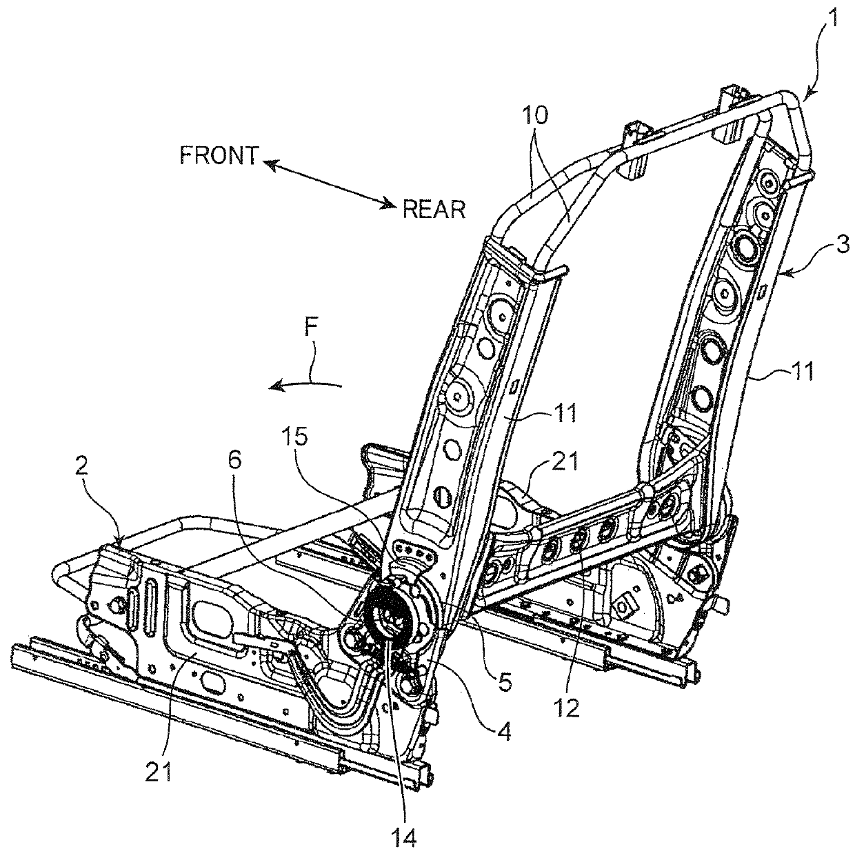
[0036]Each of the side frames 11 and the reinforcing member 12 is a press-formed product reinforced by a concavoconvex rib configuration. In particular, as illustrated in FIG. 4B, each of the side frames 11 is prepared by superimposing two plates (an inner panel 11a and an outer panel 11b) each having a thickness of about 0.5 mm. As illustrated FIG. 6B, the inner panel 11a is formed such that an end 11c thereof wraps and clamps an outer surface of an end 11d of the outer panel 11b to provide more strongly reinforced frame structure. In a welded structure according to the present invention, the side frame 11 (upper bracket 5) falls into the concept of the term “thin plate component (thin metal component)”.

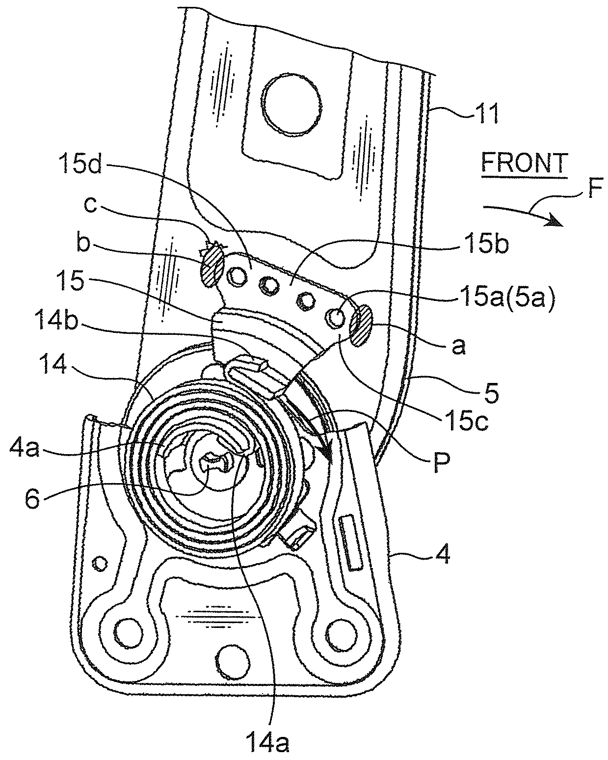
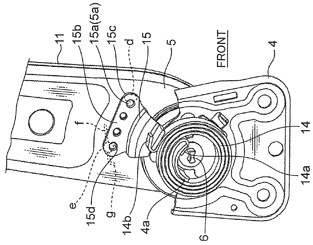
[0037]As illustrated in FIG. 2, a spiral spring 14 is provided in concentric relation to the reclining shaft 6 to bias the back frame 3 in a forward direction F so as to allow the back frame 3 to be tilted forwardly. The spiral spring 14 has an inner end 14a locked by a spring-retai...

second embodiment

[0057]Specifically, as illustrated in FIGS. 5A and 5B, each of right and left ends 12a of the reinforcing member 12 is brought into contact with an obverse surface of a laterally protruding portion 11f of a respective one of the right and left side frames 11. In the second embodiment, the side frame 11 falls into the concept of the term “thin plate component (thin metal component)”, and the reinforcing member 12 falls into the concept of the term “another component (another metal component)”.

[0058]The terms “thin plate component” and “another component” are recited, respectively, as “first component” and “second component” in the appended claims. In this connection, it should be noted that, as used in this specification, the term “thin plate component (first component)” does not mean the entirety thereof essentially has a thickness less than that of “another component (second component)”, but means at least a portion thereof around a weld zone has a thickness less than that of “anot...

third embodiment

[0072]Alternatively, the present invention may be applied to a welded structure between an aftermentioned side frame 21 and an aftermentioned cushion pan 22 of the cushion frame 2, as in a third embodiment illustrated in FIGS. 8A to 9 C.

[0073]The cushion frame 2 comprises a front section composed of a cushion pan (front reinforcing member) 22, and a side section composed of right and left side frames 21 each having an upper portion arc-welded to a respective one of right and left regions of a front bottom portion of the cushion pan 22, and a rear section composed of a reinforcing member 23 arc-welded between respective rear ends of the right and left side frames 21.

[0074]Each of the cushion pan 22 and the reinforcing member 23 is a press-formed product reinforced by a concavoconvex rib configuration. Each of the side frames 21 is formed using one thick plate. In the third embodiment, the side frame 21 falls into the concept of the term “another component (another metal component)”.

[...


PUM

PropertyMeasurementUnit
thicknessaaaaaaaaaa
thicknessaaaaaaaaaa
lengthaaaaaaaaaa

Abstract

A vibration mode control method for a thin plate-reinforcement structure utilizes a reinforcing effect of a weld bead, wherein the thin plate-reinforcement structure comprises two welded components at least one of which includes a thin plate portion. After a first (thin plate) component and a second (another) component are arc-welded discontinuously at several positions, a stress direction and level in one of the resulting weld areas located to be subject to stress concentration is preliminarily verified. Then, a stress-dispersing weld bead (f) is laid to extend between the weld area which is an area subject to stress concentration and the first (thin plate) component, wherein the stress-dispersing weld bead (f) is set to a direction and length capable of preventing fatigue crack from occurring in the first (thin plate) component.

Description

BACKGROUND OF THE INVENTION[0001]1. Field of the Invention[0002]The present invention relates to a thin plate-reinforcement structure utilizing a stiffening or reinforcing effect of a weld bead, and a method of producing the thin plate-reinforcement structure.[0003]2. Description of the Related Art[0004]Heretofore, as illustrated in FIGS. 10A and 10B, there has been known a welded structure, for example, for a seat back of an automobile seat, in which right and left end faces 31a of a lower frame 31 are bridgingly arc-welded, respectively, to right and left planar portions 30a of a pipe frame 30, wherein a continuous weld bead 32 to be provided along an upwardly and downwardly extending edge of each of the end faces 31a of the lower frame 31 is formed to additionally extend onto a respective one of the planar portions 30a of the pipe frame 30 (see JP 62-259676A: hereinafter referred to as Patent Document 1).[0005]The reason for providing an extension portion 32a to the weld bead 32 ...

Claims


Application Information

Patent Timeline
Patent Type & Authority Patents(United States)
IPC IPC(8): B23K31/02B60N2/68B23K9/02B23K9/00B60N2/20
CPCB23K31/02B23K9/0026B23K9/0043B60N2/20B60N2/68B60N2/682B23K2201/006B23K2101/006
Inventor KUSHIYAMA, TOSHIYASUGIMOTO, EIJI
Owner DELTA KOGYO CO LTD
Why Eureka
Try Eureka