Supercharge Your Innovation With Domain-Expert AI Agents!

Interbody fusion implant and related methods

a fusion implant and interbody technology, applied in the field of implants, can solve the problems of delayed bony growth or incomplete bony growth, affecting the individual's chronic pain, disabling and uncontrollable, etc., and achieve the effect of reducing the likelihood, and facilitating the introduction of the base member

Active Publication Date: 2016-01-12
ALPHATEC SPINE INC
View PDF8 Cites 0 Cited by
  • Summary
  • Abstract
  • Description
  • Claims
  • Application Information

AI Technical Summary

Benefits of technology

This approach enhances safety by protecting neural and vascular structures, allows for more efficient endplate preparation, reduces the risk of implant subsidence, and enables aggressive packing of fusion materials, leading to improved fusion outcomes and reduced procedural time.

Problems solved by technology

Various traumatic events and / or degenerative conditions may result in undesirable motion or change in disc height, both of which may cause chronic pain for the affected individual.
The degree and treatment of pain varies by the individual but in many instances the pain can be disabling and uncontrollable by conservative means, leaving surgery as the only viable option.
Not removing the cartilaginous end plate can result in a delayed bony growth or incomplete bony growth, while fracturing the bony end plate can result in a fracture of the vertebral body and post-operative settling of the implant with concomitant loss of disc height and / or vertebral body alignment.
Repetitive insertion of instruments into the disc space during the process of final endplate preparation can result in possible injury to the neural and vascular structures surrounding the disc space if the instruments are inadvertently passed or extended outside the disc space by the surgeon.
Based on the oftentimes high amount of force required to be applied to the corresponding insertion tools, such fusion promoting substances can become loosened or dislodged during the introduction of the implant, which can in certain instances increase the amount of time required to achieve fusion.
Before 2003, interbody fusion via a lateral approach was uncommon because of the inability to safely pass through the psoas muscle, which flanks either side of the lumbar spine and includes the lumbar plexus.

Method used


Image

  • Interbody fusion implant and related methods
  • Interbody fusion implant and related methods
  • Interbody fusion implant and related methods

Examples


Embodiment Construction

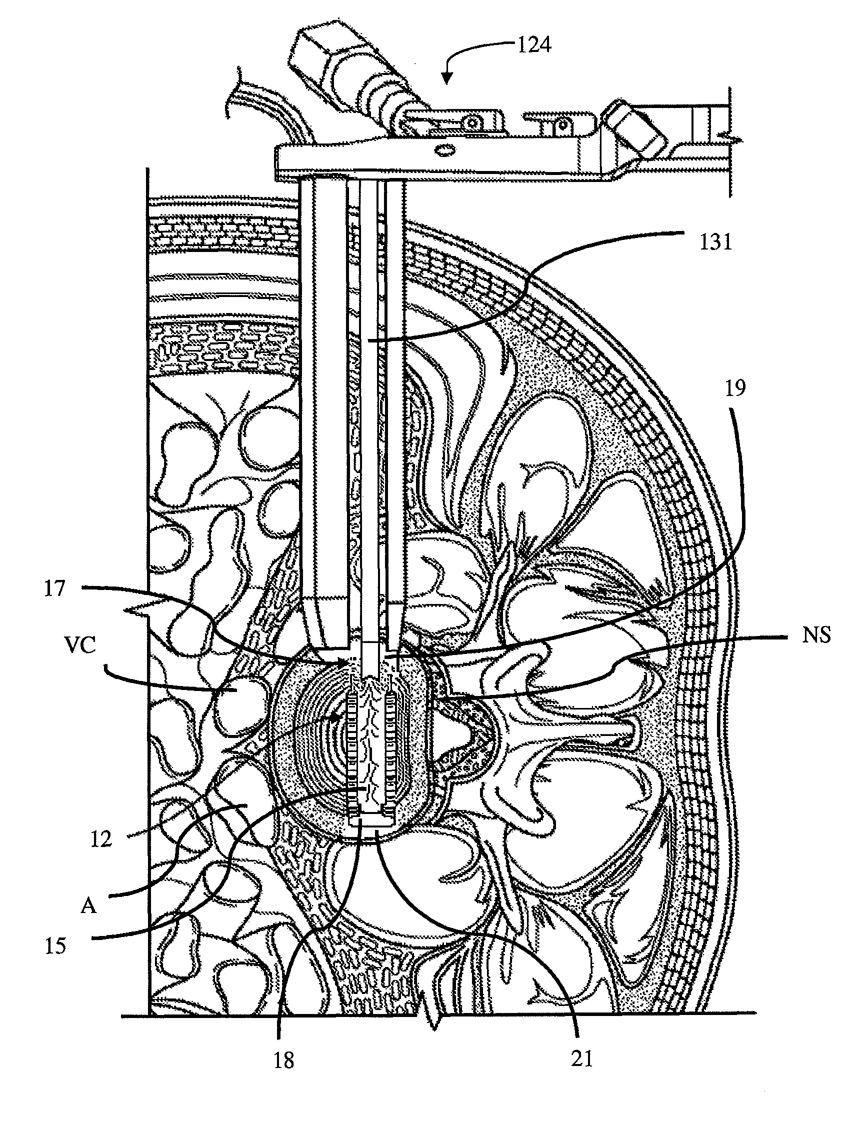
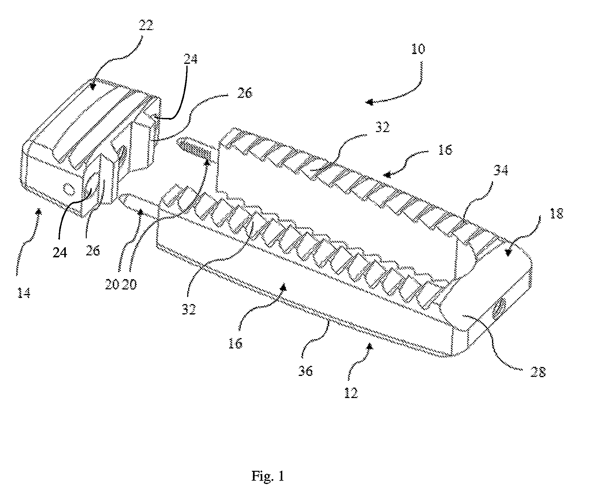
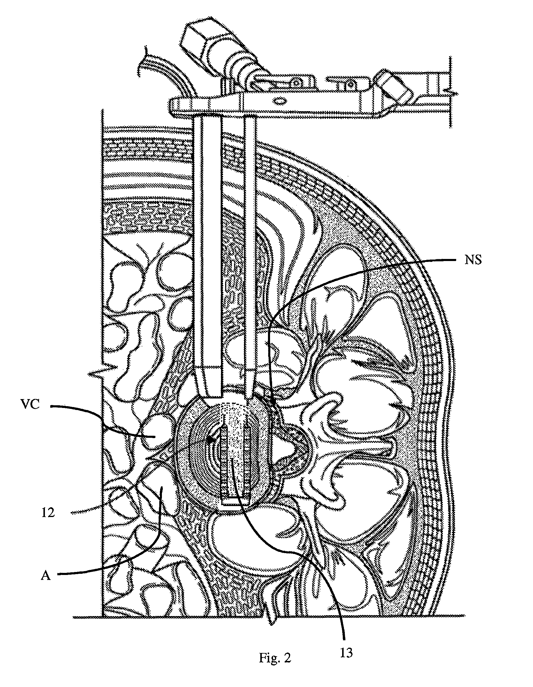
[0051]Illustrative embodiments of the invention are described below. In the interest of clarity, not all features of an actual implementation are described in this specification. It will of course be appreciated that in the development of any such actual embodiment, numerous implementation-specific decisions must be made to achieve the developer's specific goals, such as compliance with system-related and business-related constraints, which will vary from one implementation to another. Moreover, it will be appreciated that such a development effort might be complex and time-consuming, but would nevertheless be a routine undertaking for those of ordinary skill in the art having the benefit of this disclosure. The interbody implant, inserters, and associated methodology for spinal fusion using a lateral approach to the spine disclosed herein boasts a variety of inventive features and components that warrant patent protection, both individually and in combination.

[0052]FIG. 1 is a pers...


PUM


Abstract

An implant for performing interbody fusion within a human spine, inserters for such an implant, and associated methodology. The implant is preferably formed in situ from at least two separate but lockable members (a base member and a closure member). The base member may be implanted into an interbody space first, after which the end plates may be finally prepared and the base member packed with fusion promoting substances before engaging and locking the closure member. The closure member provides structural support for the adjacent vertebral bodies (along with the base member) and may be selected after implantation of the base member having a specific length, width, height, taper, etc. . . . to ensure an optimal sizing of the implant for desired restoration of disc height, coronal taper, sagittal taper, etc. . . . .

Description

CROSS REFERENCE TO RELATED APPLICATIONS[0001]The present application is a divisional of U.S. patent application Ser. No. 12 / 834,855, filed Jul. 12, 2010, which claims benefit of U.S. Provisional Application No. 61 / 224,887, filed Jul. 12, 2009, the contents of which are incorporated in full herein by reference.BACKGROUND OF THE INVENTION[0002]1. Field of Invention[0003]The present invention relates to an implant for performing interbody fusion within a human spine, inserters for such an implant, and associated methodology. More specifically, the implant aspect of the present invention involves an implant formed in situ from at least two separate but lockable members (a base member and a closure member), wherein: (a) the base member may be implanted into an interbody space first, after which the end plates may be finally prepared and the base member packed with fusion promoting substances before engaging and locking the closure member; and (b) the closure member provides structural su...

Claims


Application Information

Patent Timeline
Patent Type & Authority Patents(United States)
IPC IPC(8): A61F2/44A61F2/46A61F2/30A61F2/28
CPCA61F2/4455A61F2/442A61F2/447A61F2/4611A61F2002/2817A61F2002/2835A61F2002/305A61F2002/3008A61F2002/30176A61F2002/30266A61F2002/30299A61F2002/30429A61F2002/30467A61F2002/30471A61F2002/30492A61F2002/30504A61F2002/30509A61F2002/30607A61F2002/30611A61F2002/30616A61F2002/30774A61F2002/30777A61F2002/30779A61F2002/30825A61F2002/30828A61F2002/30904A61F2002/4629A61F2002/4687A61F2002/30507A61F2002/30604A61F2230/0082A61F2250/006A61F2002/30265A61F2002/30331A61F2002/30481A61F2002/30593A61F2002/30622
Inventor ETMINAN, MOHAMMAD
Owner ALPHATEC SPINE INC
Features
  • R&D
  • Intellectual Property
  • Life Sciences
  • Materials
  • Tech Scout
  • Unparalleled Data Quality
  • Higher Quality Content
  • 60% Fewer Hallucinations
Learn More