Spectrometer

a spectrometer and light source technology, applied in the field of spectrometers, can solve the problems of difficult recognition of measurement targets, inability to easily specify the position of light sources, and the influence of ambient light included in the spectrum of measurement targets, so as to reduce the influence of ambient light, and improve the accuracy of recognizing measurement targets

Inactive Publication Date: 2016-01-12
TOYOTA JIDOSHA KK +1
View PDF45 Cites 24 Cited by
  • Summary
  • Abstract
  • Description
  • Claims
  • Application Information

AI Technical Summary

Benefits of technology

[0006]An objective of the present invention is to provide a spectrometer capable of removing or reducing influence of an ambient light included in a reflected light spectrum of a measurement target with a simple structure, and capable of further increasing accuracy for recognizing the measurement target.

Problems solved by technology

However, generally the ambient light is not always the light from a specific light source particularly in an environment of outdoors.
When the measurement target is moved, a position of the light source cannot be easily specified even if there is only one light source.
Thus, in a general environment where the ambient light possibly irregularly varies, there is also a high possibility that the influence of the ambient light included in the spectrum of the measurement target cannot be removed or reduced.
Namely, even if various kinds of measurement targets that exist around a vehicle is desired to be recognized using the spectral data measured by the aforementioned spectral sensor, it is difficult to recognize measurement targets, which are requested to be recognized for supporting driving of the vehicle, due to low accuracy in recognizing the measurement target under the influence of the ambient light, wherein the measurement target.

Method used


Image

  • Spectrometer
  • Spectrometer
  • Spectrometer

Examples


first embodiment

[0032]the present invention will now be described with reference to the drawings.

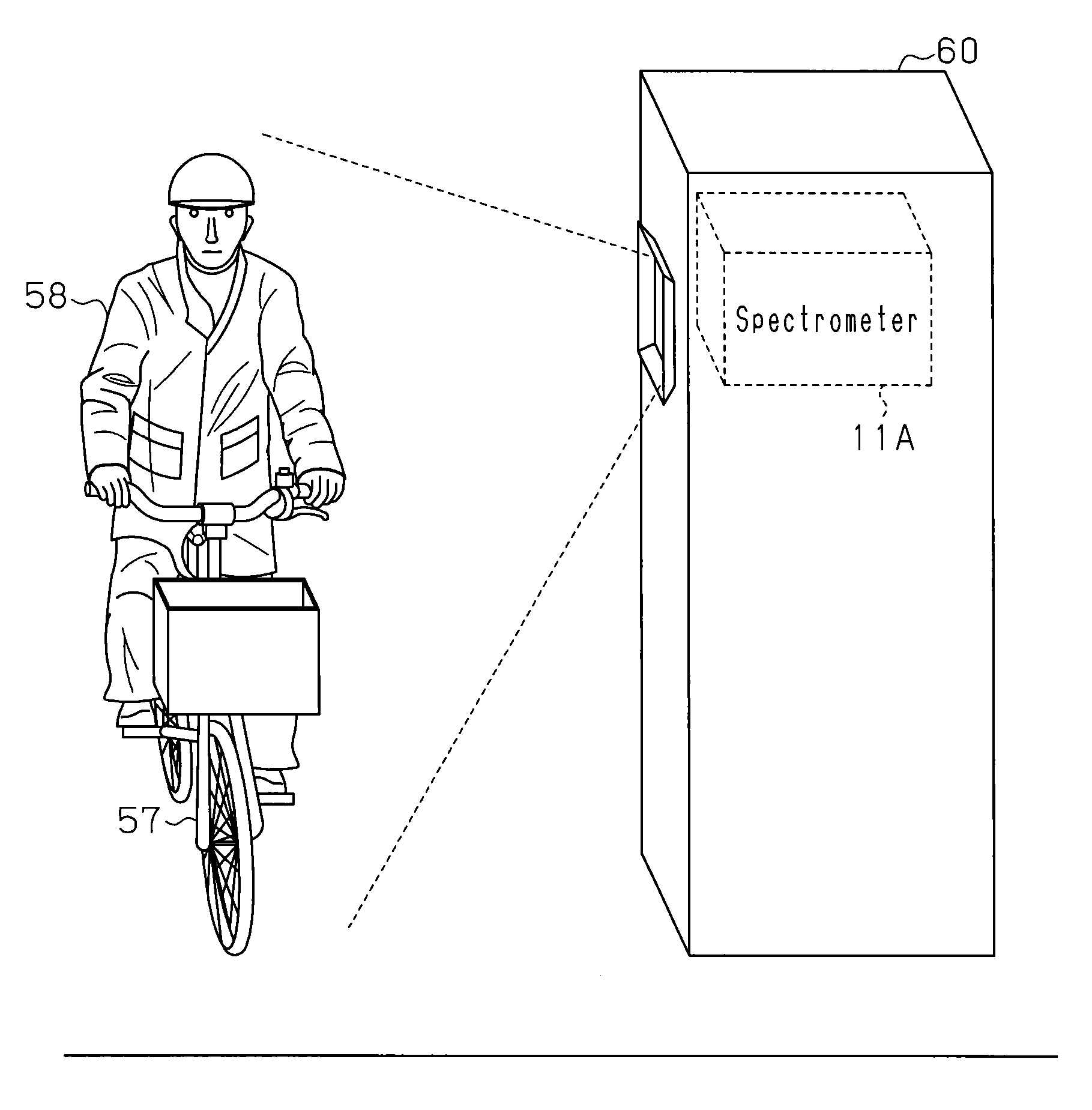
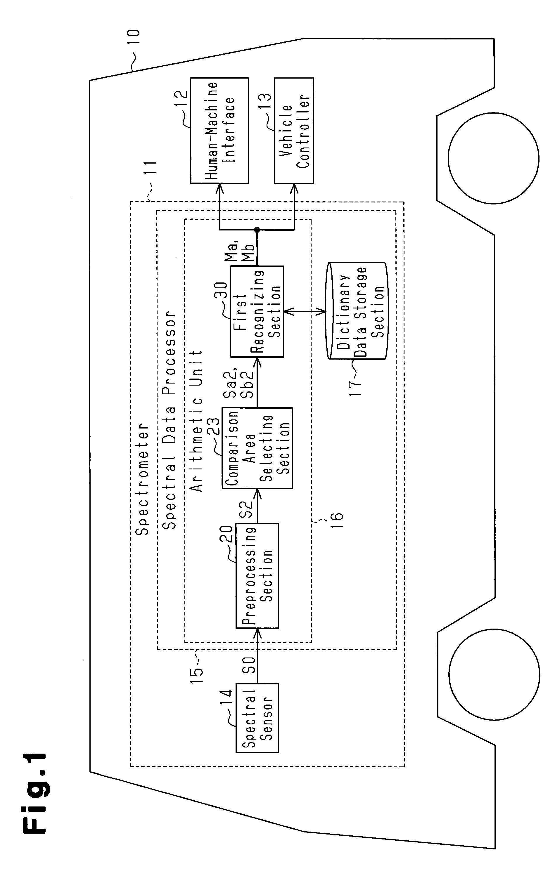
[0033]As shown in FIG. 1, a spectrometer 11 of this embodiment is provided in a vehicle 10, which is a moving body. The spectrometer 11 recognizes a measurement target by acquiring light information including a visible light and an invisible light outside of the vehicle 10. Further, the vehicle 10 includes a human-machine interface 12 for transmitting recognition information and the like output from the spectrometer 11 to occupants of the vehicle 10, and a vehicle controller 13 for reflecting the recognition information and the like output from the spectrometer 11 to control of the vehicle 10.

[0034]The human-machine interface 12 is a known interface device including operating units such as push buttons or a touch panel, so that a vehicle state and the like is transmitted to occupants, particularly the driver, through light, colors, and sound, so that the intention of an occupant is input to the spectrom...

third embodiment

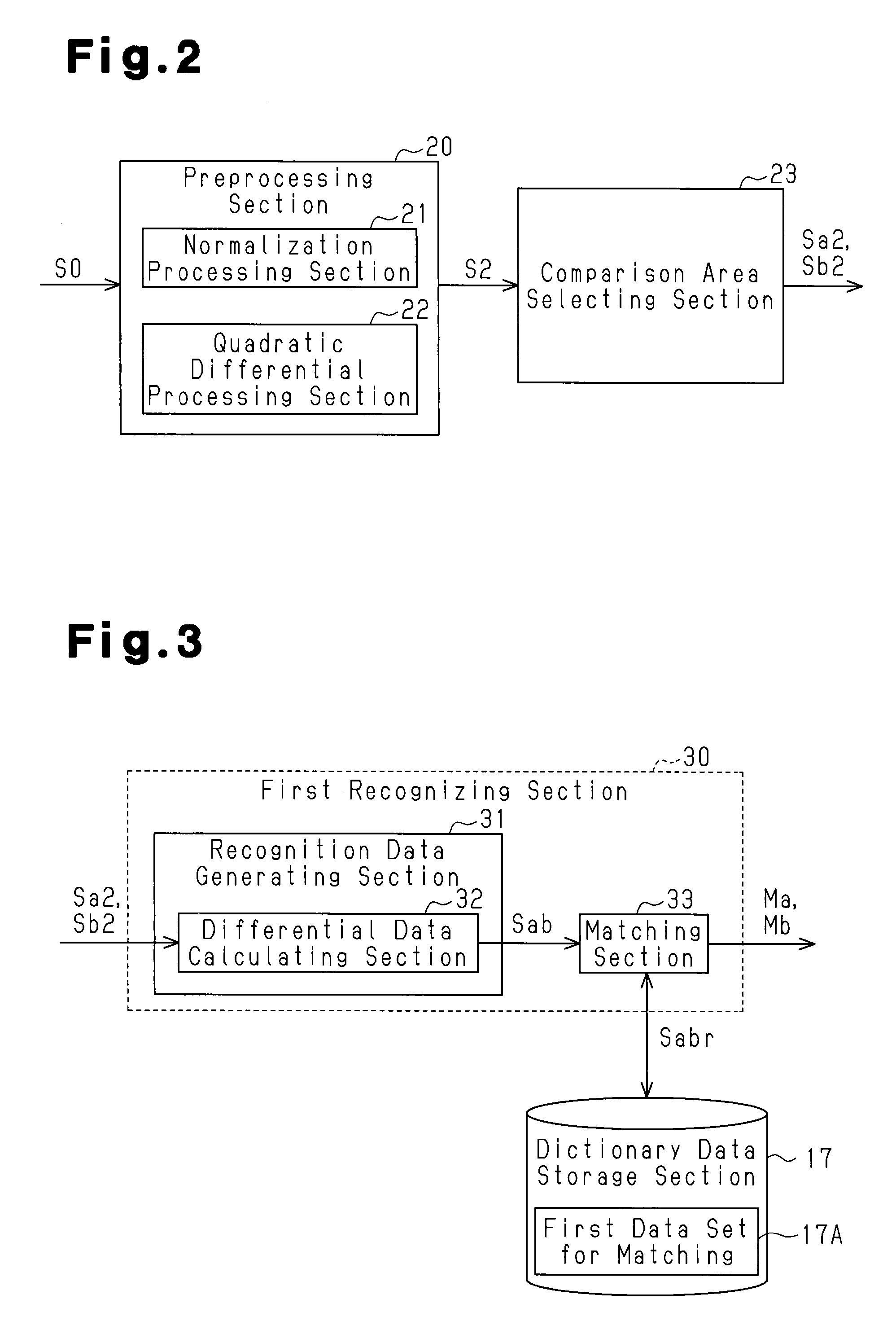
[0101]As shown in FIG. 18, the arithmetic unit 16 of this embodiment includes the boundary area selecting section 25 and the fourth recognizing section 37 in addition to the preprocessing section 20, the comparison area selecting section 23, and the first recognizing section 30. The boundary area selecting section 25 of this embodiment is the same as the boundary area selecting section 25 described in the third embodiment, and therefore description thereof is omitted.

[0102]The fourth recognizing section 37 removes the ambient light included in each of the comparison boundary position spectral data sets Sp2 and Sq2. The fourth recognizing section 37 is connected to the boundary area selecting section 25. The fourth recognizing section 37 includes a recognition data generating section 42 and a matching section 43. If compared with the recognition data generating section 31 of the first embodiment, the recognition data generating section 42 is different from the recognition data genera...

second embodiment

[0115]The aforementioned second embodiment shows a case, for example, in which the correlation spectral data set Sab is calculated by the second recognizing section 35, by division processing using two comparison position spectral data sets Sa2 and Sb2. However, the present invention is not limited thereto, and if the ambient light included in the two comparison position spectral data sets can be removed or reduced, the difference between the two comparison position spectral data sets may be obtained as the correlation spectral data set.

[0116]In each of the aforementioned embodiments, the dictionary data storage section 17 stores the first data set for matching 17A regarding the combination of the spectral data sets of a plurality of measurement targets. However, the present invention is not limited thereto, and the dictionary data storage section 17 may store the data set for matching based on the spectral data set of one measurement target respectively. In this case, by selecting ...


PUM


Abstract

A spectrometer recognizes a measurement target on the basis of the spectral data set of observed light detected by a spectral sensor capable of measuring wavelength information and light intensity information. The spectrometer is provided with a spectral data processor. Spectral data sets are detected at two different positions by the spectral sensor, and the processor subtracts a first spectral data set from a second spectral data set, or divides the first spectral data set by the second spectral data set to calculate one phase correlation spectral data set, which is correlated to the spectral data sets at the two different positions. The processor simultaneously identifies the measurement target corresponding to the two different positions on the basis of the correlation spectral data set.

Description

FIELD OF THE INVENTION[0001]The present invention relates to a spectrometer that recognizes a measurement target that exists in the surrounding environment, in particular, that exists in a traffic environment, based on spectral data obtained by measuring this measurement target by a spectral sensor.BACKGROUND OF THE INVENTION[0002]In recent years, efforts have been made toward practical use of a technique for recognizing a measurement target that is measured by a spectral sensor and exists in the surrounding environment of the spectral sensor from multispectral data including a visible light region and an invisible light region, and providing various kinds of support in accordance with the recognized measurement target or its state. For example, for vehicles such as automobiles, a drive support device has been examined for practical application that recognizes pedestrians or other vehicles that exist in the surrounding traffic environment of the vehicle based on spectral data measur...

Claims


Application Information

Patent Timeline
Patent Type & Authority Patents(United States)
IPC IPC(8): G01J3/28G01J1/42G01J3/457G01J3/02G08G1/16G06K9/00
CPCG01J3/457G01J1/4204G01J3/027G01J3/0264G01J3/2823G06K9/00791G06K9/00805G08G1/166G06K2009/00644G06V40/103G06V20/194G06V20/56G06V20/58
Inventor KAWAMATA, SHINYAFUNAYAMA, RYUJIISHI, TSUTOMUYOSHIKAWA, YUMIKO
Owner TOYOTA JIDOSHA KK
Why Eureka
Try Eureka