Supercharge Your Innovation With Domain-Expert AI Agents!

Current mode step-down switching regulator

a switching regulator and current mode technology, applied in the direction of electric variable regulation, process and machine control, instruments, etc., can solve the problems of duty not being reduced to a level equal or smaller, exerting an influence, etc., to reduce an influence, reduce an influence, and enhance the effect of over-current limiting characteristics

Active Publication Date: 2016-01-12
ABLIC INC
View PDF4 Cites 0 Cited by
  • Summary
  • Abstract
  • Description
  • Claims
  • Application Information

AI Technical Summary

Benefits of technology

The present invention offers a solution for reducing the impact of response delay in a comparator, by simulating the effect of reducing the oscillulation frequency in an over-current state. This results in improved over-current limiting characteristics, even when the output voltage is reduced.

Problems solved by technology

However, in practice, the comparator has a delay time, and the delay time exerts an influence on Duty.
However, when Duty becomes small, the influence by the delay time in the comparator cannot be disregarded.
In the case of the conventional circuit shown in FIG. 6, there is encountered a problem in that when the output voltage VOUT is low, Duty cannot be reduced to a level equal to or smaller than the delay time in some cases due to the influence by the response delay of the comparator, and hence the over-current limiting function cannot operate.
When the current limiting function does not operate, there arises a problem in that the current caused to flow into the coil 109 and the current caused to flow through the switching element 107 cannot be limited.
Also, when the current exceeds an allowable current value, it becomes impossible to obtain the original inductance value.

Method used


Image

  • Current mode step-down switching regulator
  • Current mode step-down switching regulator
  • Current mode step-down switching regulator

Examples


Embodiment Construction

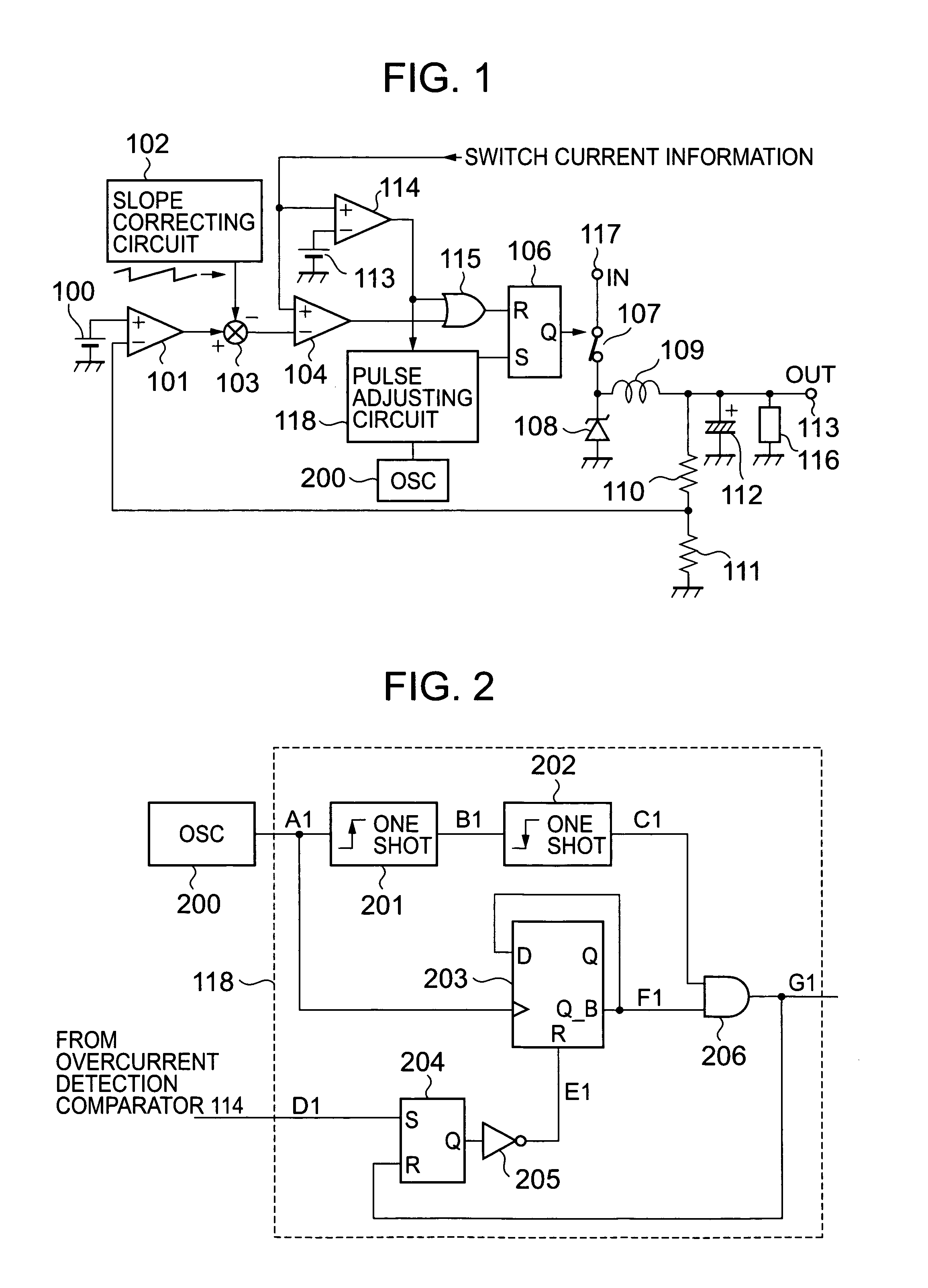
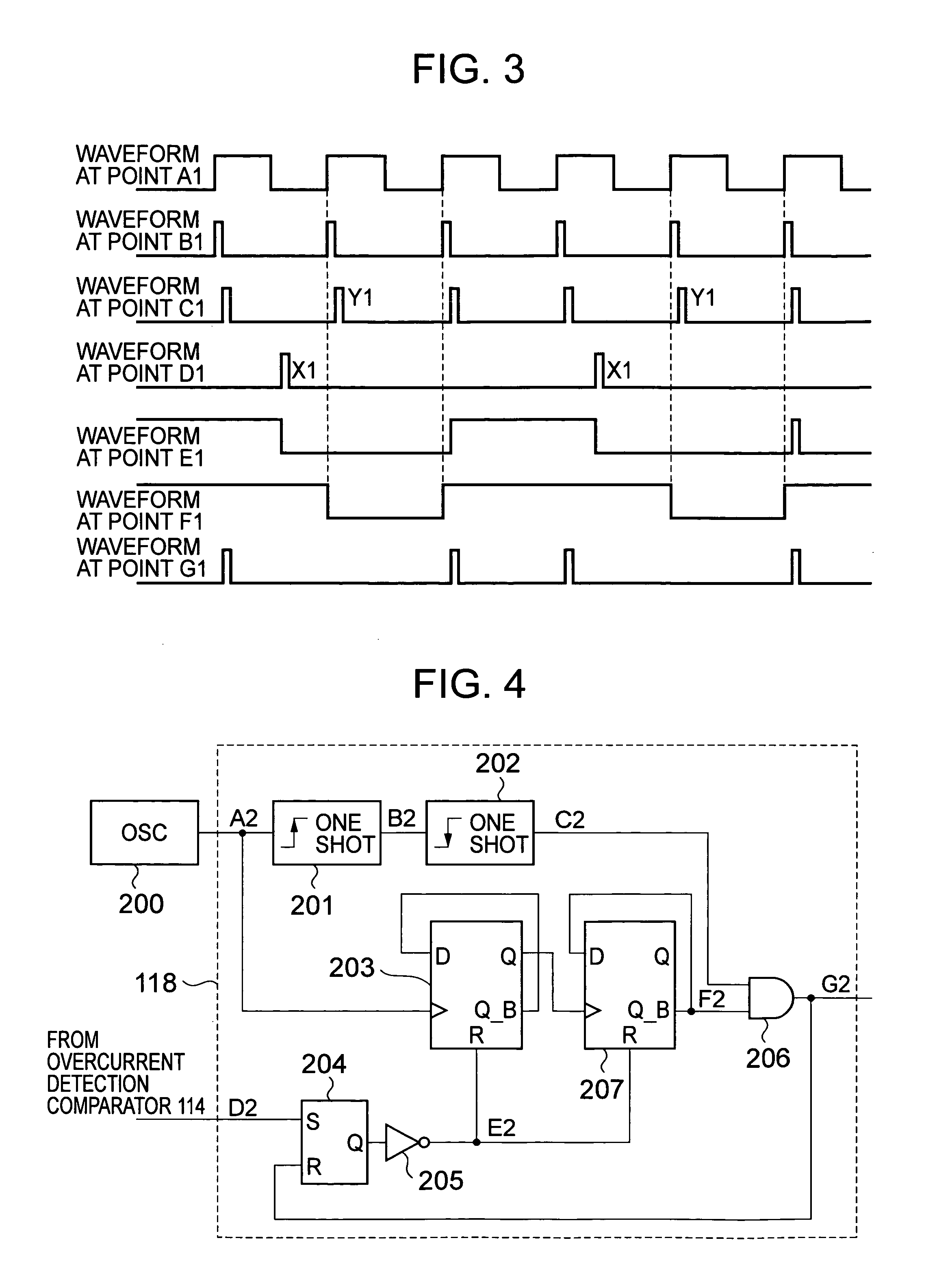
[0027]An arbitrary number of pulses are skipped which are inputted to a set terminal of an SR-latch right after a pulse is outputted from an over-current detecting comparator in an over-current state, whereby there is offered an effect equivalent to a case where an oscillation frequency is reduced, and thus an influence by response delay in an over-current detecting comparator is reduced, and thus over-current limiting characteristics when an output voltage VOUT is low are enhanced.

[0028]An embodiment of the present invention will hereinafter be described with reference to the accompanying drawings.

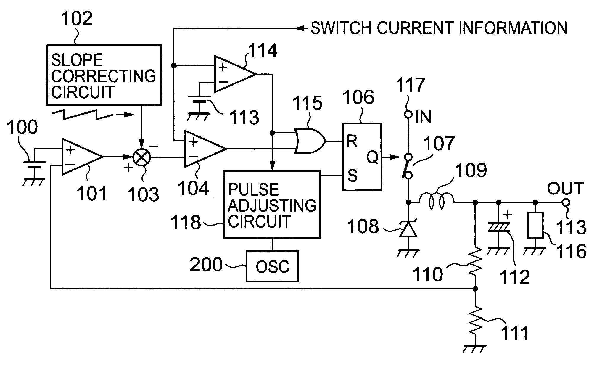
[0029]FIG. 1 is a circuit diagram showing a construction of a current mode step-down switching regulator according to an embodiment of the present invention.

[0030]A switch 107 serves to a supply an input voltage VIN to a coil 109. An error amplifier 101 amplifies a difference between a voltage obtained by dividing an output voltage VOUT at an output terminal 113 with a first resistor 110 ...


PUM


Abstract

Provided is a current mode step-down switching regulator which is capable of enhancing over-current limiting characteristics even when an over-current limiting function operates to reduce an output voltage. The current mode step-down switching regulator includes a pulse adjusting circuit. When an over-current is detected, a switching output signal is thinned out by the pulse adjusting circuit to be outputted in order to reduce an apparent oscillation frequency, thereby reducing an influence by response delay in an over-current detecting comparator.

Description

BACKGROUND OF THE INVENTION[0001]1. Field of the Invention[0002]The present invention relates in general to a current mode step-down switching regulator, and more particularly to an over-current limiting circuit of a current mode step-down switching regulator.[0003]2. Description of the Related Art[0004]FIG. 6 shows a circuit diagram of an over-current limiting circuit of a conventional current mode step-down switching regulator. A switch 107 serves to supply an input voltage VIN to a coil 109. An error amplifier 101 amplifies a difference between a voltage obtained by dividing an output voltage VOUT at an output terminal 113 with a first resistor 110 and a second resistor 111, and a reference voltage VREF supplied from a reference voltage source 100.[0005]A signal which is obtained by subtracting a correction ramp wave outputted from a slope correcting circuit 102 from an output signal from the error amplifier 101 in a subtracter 103 is inputted to an inverting input terminal of a ...

Claims


Application Information

Patent Timeline
Patent Type & Authority Patents(United States)
IPC IPC(8): H02H7/00H02H7/12H02M3/156H02M1/00H02M3/155
CPCH02H7/1213H02M3/156H02M2001/0025H02M1/0025
Inventor FUKUI, ATSUO
Owner ABLIC INC
Features
  • R&D
  • Intellectual Property
  • Life Sciences
  • Materials
  • Tech Scout
  • Unparalleled Data Quality
  • Higher Quality Content
  • 60% Fewer Hallucinations
Learn More