Optical element providing oblique illumination and apparatuses using same

a technology of optical elements and oblique illumination, applied in the field of optical elements, can solve the problems of poor illumination of the billboard, poor irradiance or power per unit area, uneven irradiance along the height of the billboard, etc., and achieve the effect of improving the oblique illumination of the surfa

Active Publication Date: 2016-01-19
VIAVI SOLUTIONS INC
View PDF22 Cites 14 Cited by
  • Summary
  • Abstract
  • Description
  • Claims
  • Application Information

AI Technical Summary

Benefits of technology

[0009]Accordingly, it is an object of the present invention to provide an optical element to provide improved oblique illumination of a surface, such as a billboard, or other vertical surface, having more uniformity than the prior art.
[0011]It is another object of the present invention to provide an optical element that can be used in apparatuses having one or more optical elements that are positionable along the width of a surface, spaced horizontally and vertically from the bottom, top, or side edge thereof, to provide oblique angle illumination which is at least substantially uniform in irradiance from upwards, downwards, or sideways, respectively, so as to appear uniform in illumination to human visual perception of such surface.
[0012]A still further object of the present invention is to provide an optical element that can be used in apparatuses having multiple optical elements that utilize LEDs to provide oblique illumination which is uniform (at least substantially) in spectrum (or color) along a surface so as to appear uniform in spectrum (or color) to human visual perception of such surface.
[0026]The optical elements described herein can provide improved uniformity of oblique illumination with variation of intensity of less than 2 to 1 upon a target surface, which although substantially uniform can appear uniform in illumination to human visual perception of the target surface. This is in contrast with conventional approaches to oblique illumination, such as used for billboard illumination, which at best typically varies in intensity of 6 to 1 and thus can be noticeably non-uniform to the human eye, and can make poorly lit areas of the billboard more difficult to view.
[0032]The spatial distribution of the light from the second optical elements should match (or at least substantially match) the spatial distribution of the light from the first optical elements over the portion of the target surface that is spectrally non-uniform. If needed, the second optical elements further has an additional optical element for diffusing light that provides this function. This can ensure spectral uniformity (at least in perception to the human eye) along the portion of the target surface where light from the first and second optical elements combine. Alternatively, the body of the second optical elements may each be asymmetric like the first optical element (and at the same oblique angle), with an optical element that limits (e.g., blocks, spectrally filters, or to at least minimizes) light from the second optical element being directed by the second optical element towards other portion of the target surface that already appear spectrally uniform (at least substantially) in the first color and thus does not need light from the second optical element. Also, light from adjacently disposed second optical elements may partially overlap each other to provide uniform (at least substantially) distribution of illumination of the second color along the portion of the target surface receiving such light.
[0034]Although the apparatus with the first and second optical elements is described above in connection with a billboard being the target surface, such apparatus is positionable at a distance from a bottom, top, or side edge of any target surface to provide a substantially uniform distribution of the output illumination both spectrally and in irradiance at the oblique angle along one of the dimensions of the target surface of upwards, downwards, or sideways, respectively, without obstruction of the view of the surface.

Problems solved by technology

The resulting light distribution on the billboard (irradiance, or power per unit area) is poor and can vary by 6:1 or more, and will often exhibit an undesirable scalloped pattern at the base where, directly in front of the lights, the billboard is most brightly lit and between the lights the billboard is poorly lit.
In addition, the irradiance along the height of the billboard is not uniform, decreasing significantly from the bottom to the top of the billboard.
But in doing so, the direct light passing through this center portion remains uncontrolled.
This presents a problem.
If one tries to control the direct light by manipulating the structure of the center portion of the window, then one adversely affects the path of the reflected light.
Conversely, if one tries to alter the path of the reflected light by manipulating the structure of the center portion of the window, then the direct light is adversely affected.
Both paths cannot be controlled by the same structure.
Although attempts have been made to control the reflected light by structuring the reflector and having a clear window, this allows much of the direct light to strike the billboard uncontrolled or even miss the billboard surface altogether, the consequence of this is that uniformity of the light distribution on the billboard is degraded.
It has been found that currently used metal halide lamp systems despite such attempts have poor uniformity of a 6 to 1 variation of the light irradiance across the billboard.
The lenses are not designed for the oblique illumination of a billboard or vertical surface.
Although useful to improve the overall efficiency for illumination of a billboard from that of HID lamps, the uniformity of this approach is even poorer in that the irradiance along the billboard varies from 12.6 footcandles to 99 footcandles, as stated by Heller et al., or a variation of nearly 8 to 1.

Method used


Image

  • Optical element providing oblique illumination and apparatuses using same
  • Optical element providing oblique illumination and apparatuses using same
  • Optical element providing oblique illumination and apparatuses using same

Examples


Embodiment Construction

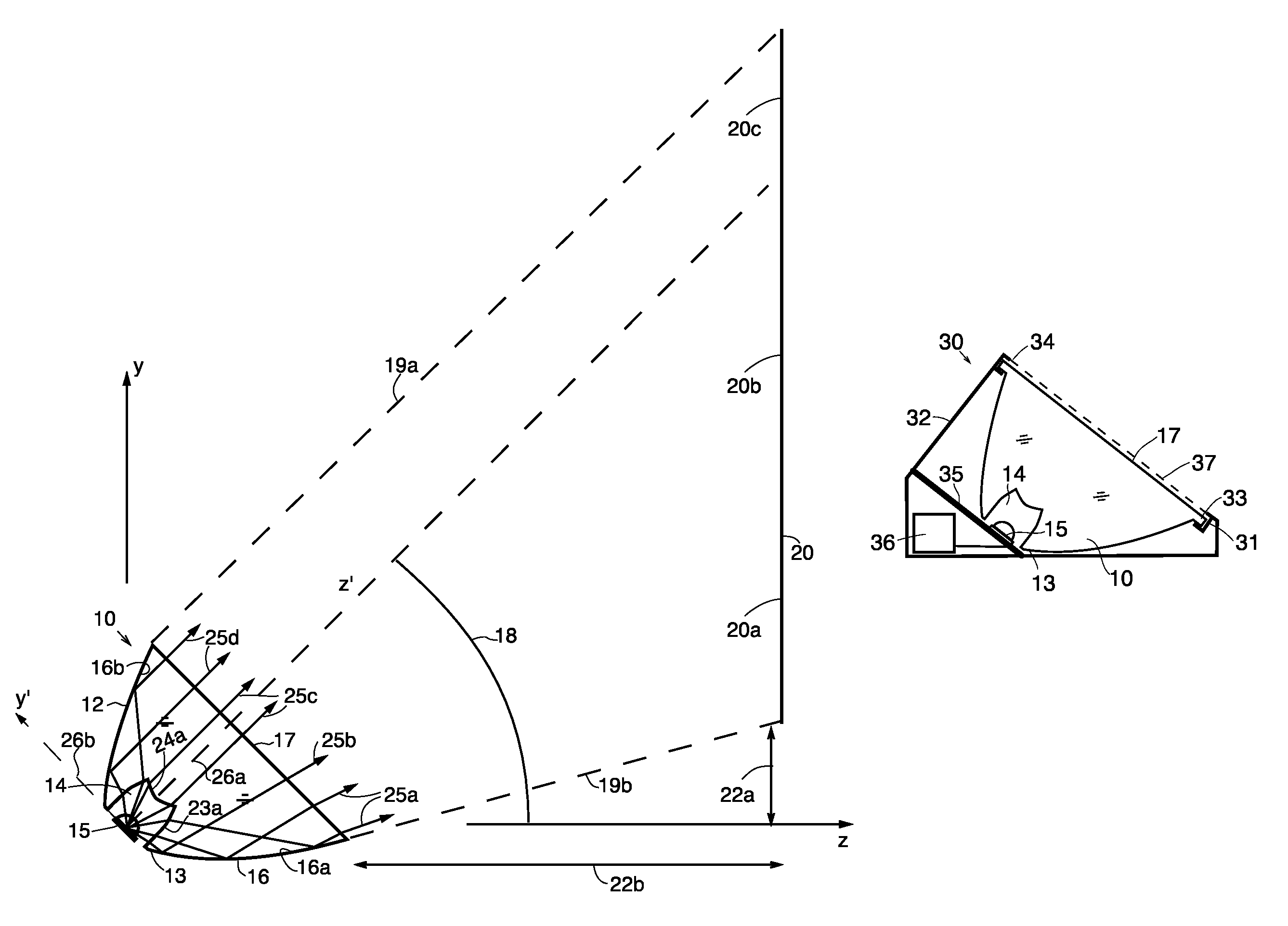
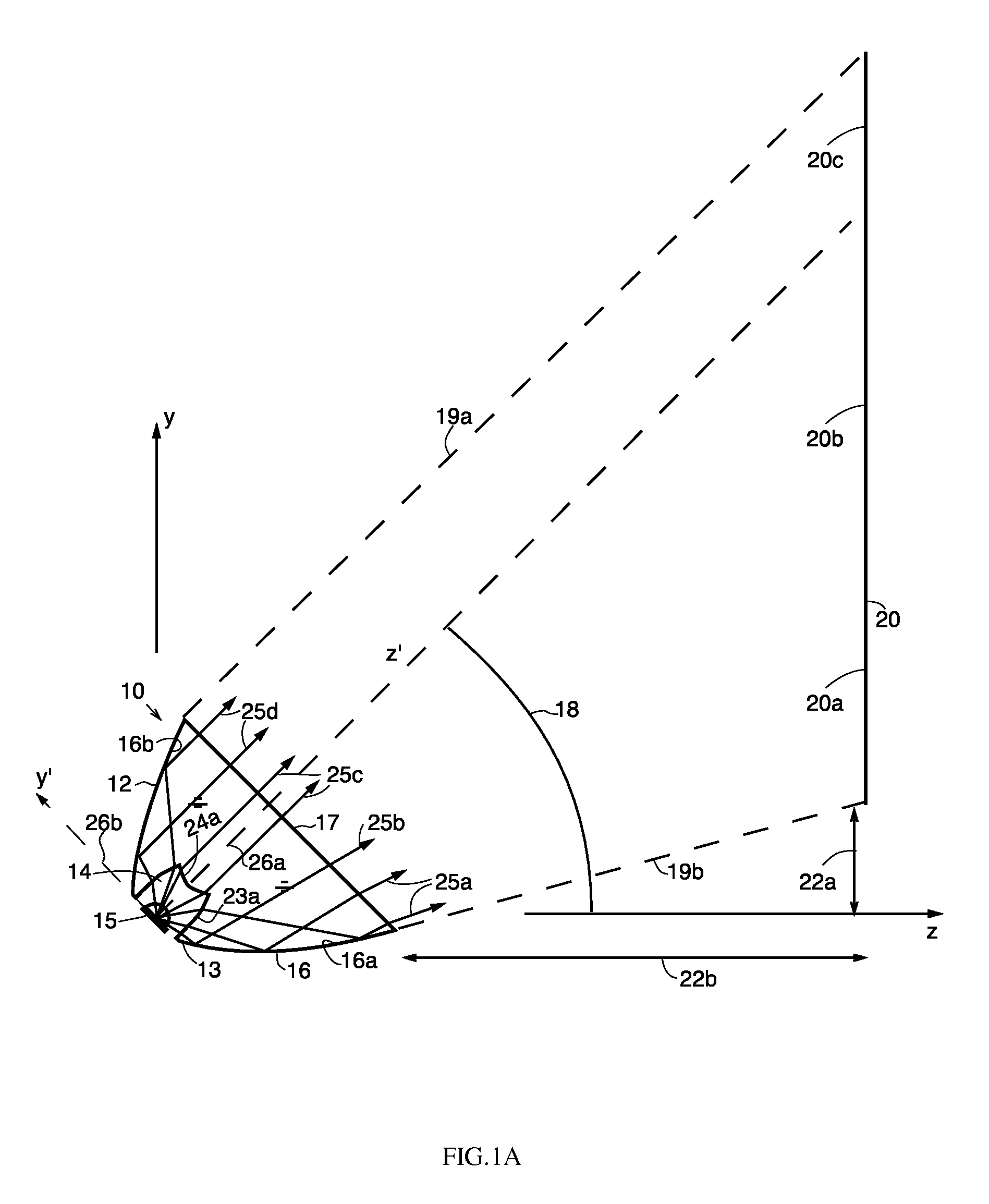
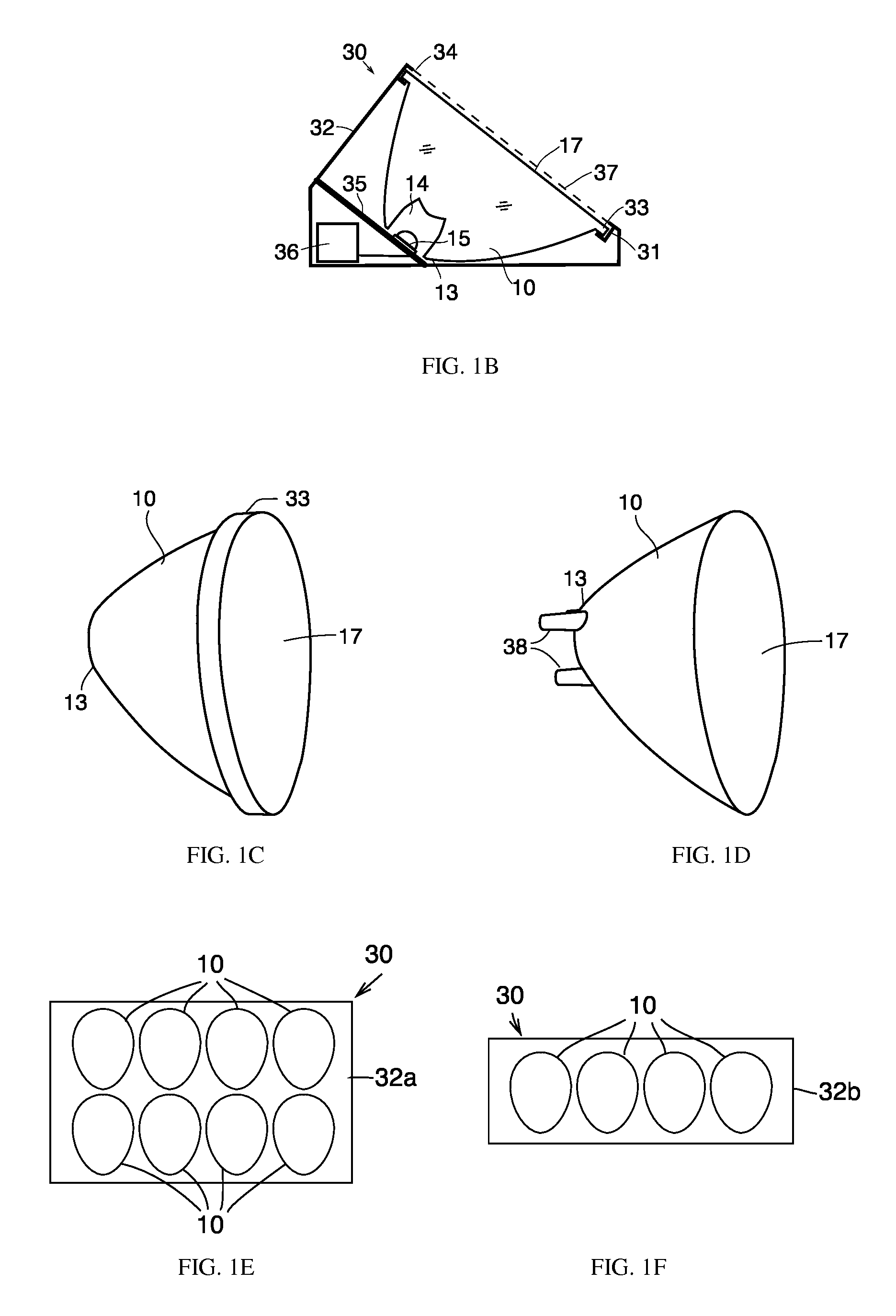
[0065]Referring to FIG. 1, the optical element 10 of the present invention is shown having a body 12 with a base 13 having a cavity or recess 14 for receiving a light source 15, e.g., LED, outer sides 16 providing total internal reflection, and a front face 17. Body 12 is positioned above light source 15, such that the light source lies within the cavity 14 and is even or nearly even with the bottom of base 13. Front surface 17 is tilted to position the optical element 10 at an oblique angle 18 with respect to a target surface 20, such as a billboard, screen, wall, or other surface desired to be illuminated. The target output illumination from the optical element 10 extends between lines 19a and 19b upwards, i.e., to the top and bottom edges of surface 20. Lines 19a and 19b are defined as the viewing angle θ, as shown in FIG. 2. The body 12 is asymmetrically (or oblong) shaped about an optical axis z′ (as opposed to being rotationally symmetric), and longer along the major axis y′, ...


PUM


Abstract

An optical element is provided having an asymmetric body, a light source, and a front face tilted at an oblique angle with respect to a target surface to provide illumination that is at least substantially uniform along the target surface's height. One or more optical elements may be in an apparatus, and multiple apparatuses may be disposed in front of one edge of a target surface to provide thereto at least substantially uniform oblique illumination. When the light source is an LED that is spectrally non-uniform at increasing angles away from its optical axis, the optical elements having such LEDs provide illumination that is spectrally non-uniform along a portion of the target surface, and additional optical elements with LED light sources are provided having a spectrum in one or more spectral ranges that compensates for such spectral non-uniformity to correct spectral non-uniformity along such portion of the target surface.

Description

CROSS-RELATED APPLICATIONS[0001]This application is a continuation-in-part of U.S. patent application Ser. No. 13 / 768,746, titled “Optical Element Providing Oblique Illumination And Apparatuses Using Same”, filed on Feb. 15, 2013, the entire contents of which are incorporated herein by reference.FIELD OF THE INVENTION[0002]The invention relates to an optical element that illuminates a surface at an oblique angle and does so such that the irradiance of the surface is uniform at least substantially over an area (e.g., height and at least a portion of width) of that surface, and apparatuses having optical element and source(s) providing illumination thereto. The optical element of the present invention is useful for applications such as illumination of a wall from a floor or ceiling position, architectural lighting, sign or billboard lighting, or any other application where the light source is not positioned directly in front of the object being illuminated but must be located at an ob...

Claims


Application Information

Patent Timeline
Patent Type & Authority Patents(United States)
IPC IPC(8): F21V5/00F21V7/00G09F13/02F21K99/00F21V7/04
CPCF21K99/00G09F13/02F21V7/0091F21V5/007F21V5/04F21V5/08F21V7/10F21V21/00F21V21/30F21W2131/107F21Y2115/10F21Y2113/13F21Y2105/10
Inventor SCHERTLER, DONALD, J.
Owner VIAVI SOLUTIONS INC
Why Eureka
Try Eureka