Joint Arthroplasty

a joint replacement and joint technology, applied in knee joints, prostheses, medical science, etc., can solve the problems of imbalance and an opening of the loose side of the joint, the knee cannot function properly, and the current balance of the joint has significant drawbacks, so as to achieve the effect of superior fit and function of the replacement join

Active Publication Date: 2016-01-26
PARRY TODD R
View PDF22 Cites 22 Cited by
  • Summary
  • Abstract
  • Description
  • Claims
  • Application Information

AI Technical Summary

Benefits of technology

[0011]The various systems and methods of the present invention have been developed in response to the present state of the art, and in particular, in response to the problems and needs in the art that have not yet been fully solved by currently available joint arthroplasty systems and methods. The systems and methods of the present invention may enable joint arthroplasty that provides superior fit and function of the replacement joint, without the need for additional risk, trauma, and recovery time.

Problems solved by technology

With respect to revision knee surgery, such surgeries generally involve removing one or more prosthetic components that were previously placed within the knee (“primary components”) but have become worn, did not fit properly, or have otherwise prevented the knee from functioning properly.
If there is lack of tension holding one side of the joint together compared to the amount of tension on the other side, this creates an imbalance and an opening of the loose side of the joint when moves through its range of motion.
A patient can often feel this extra motion, laxity, and / or imbalance as a sense of instability in the joint and it can contribute to patient dissatisfaction as well as a joint that wears out faster as it is not restrained to the smooth motion it was engineered to follow.
Techniques currently used to balance the joint have significant drawbacks.
With these cut or release techniques there is always the risk of removing too much bone or over releasing the ligament to the point of failure.
These problems can be difficult to correct, and can result in increased surgical and recovery time.

Method used


Image

  • Joint Arthroplasty
  • Joint Arthroplasty
  • Joint Arthroplasty

Examples


Embodiment Construction

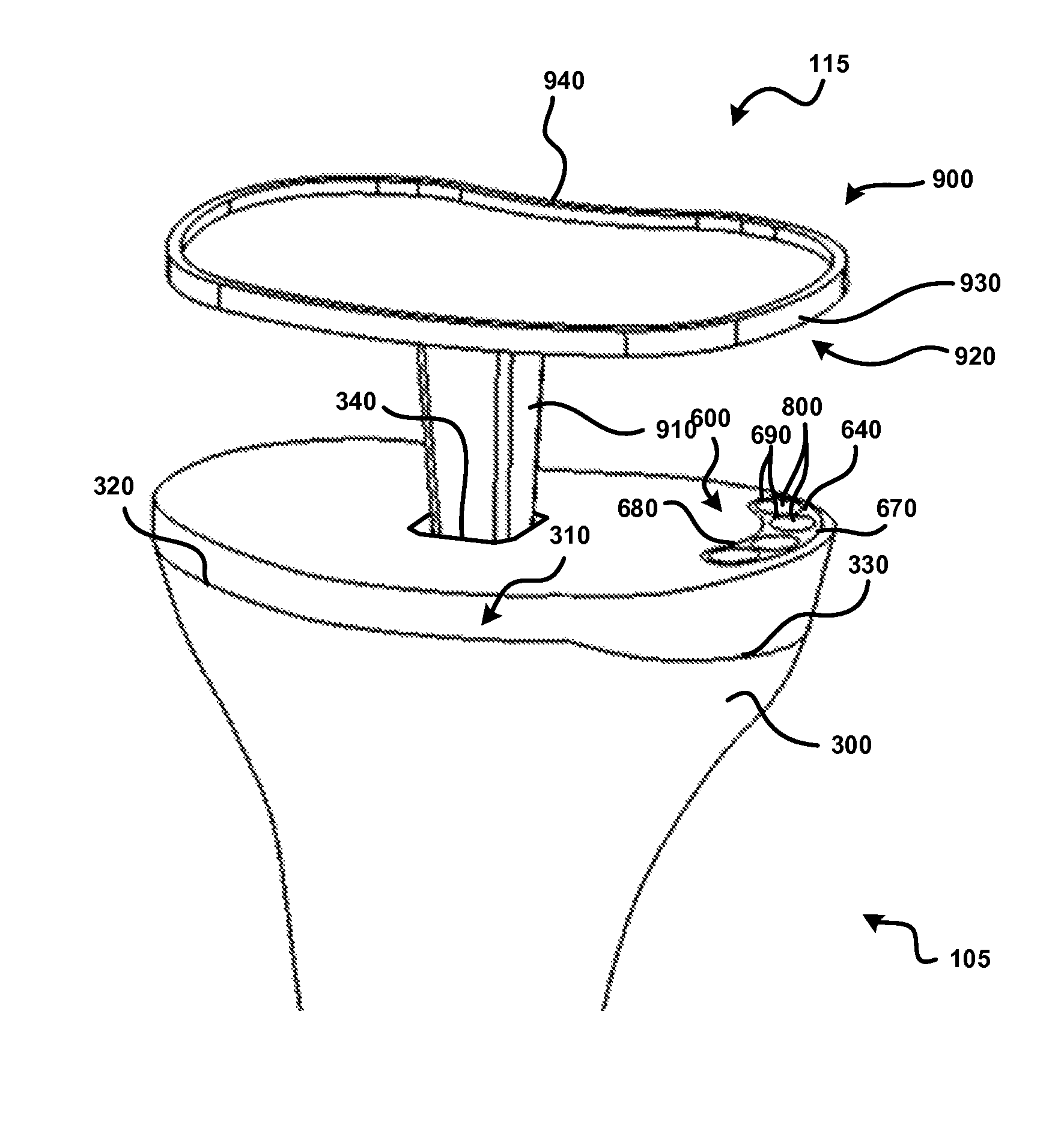
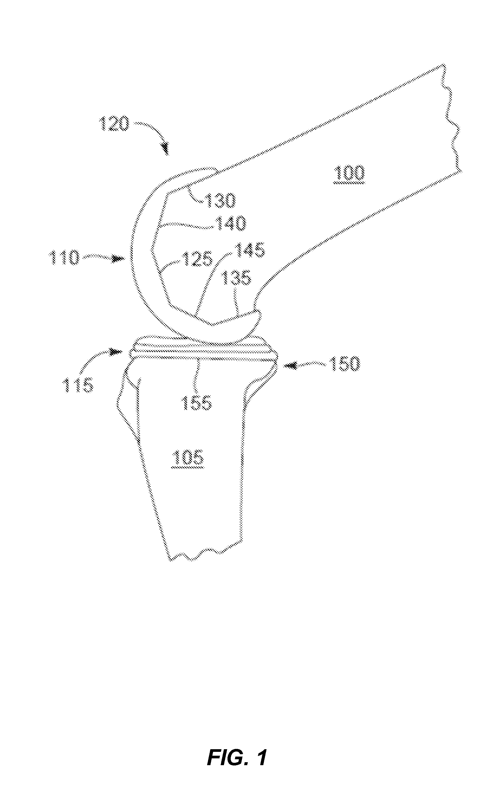
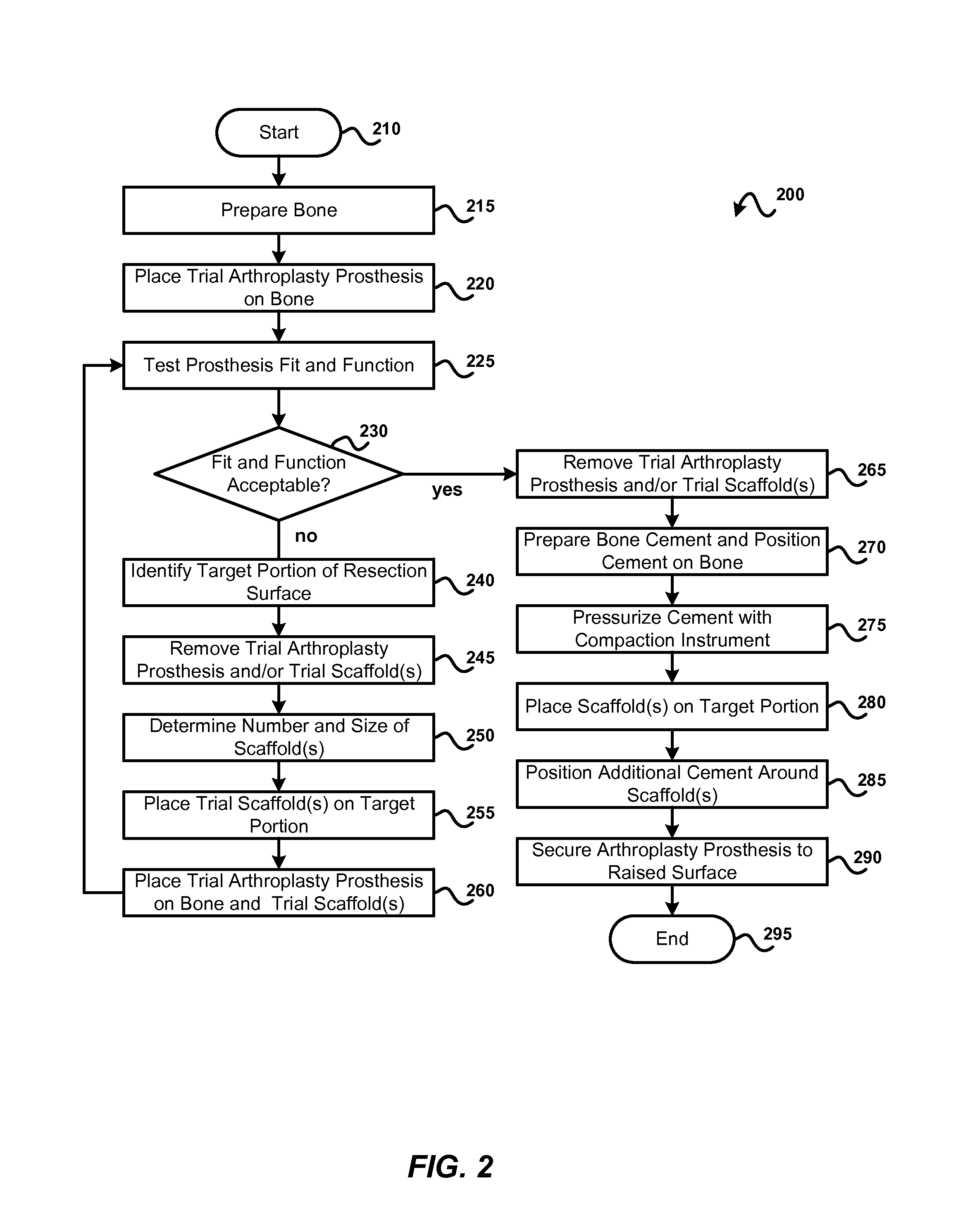
[0045]Exemplary embodiments of the invention will be best understood by reference to the drawings, wherein like parts are designated by like numerals throughout. It will be readily understood that the components of the invention, as generally described and illustrated in the Figures herein, could be arranged and designed in a wide variety of different configurations. Thus, the following more detailed description of the embodiments of the apparatus, system, and method, as represented in FIGS. 1 through 28, is not intended to limit the scope of the invention, as claimed, but is merely representative exemplary of exemplary embodiments of the invention.

[0046]The phrases “connected to,”“coupled to” and “in communication with” refer to any form of interaction between two or more entities, including mechanical, electrical, magnetic, electromagnetic, fluid, and thermal interaction. Two components may be functionally coupled to each other even though they are not in direct contact with each ...


PUM


Abstract

A system and method for joint arthroplasty may utilize one or more scaffolds to help support an arthroplasty prosthesis for the joint. A natural or prosthetic articulating surface may first be removed from one of the bones of the joint. This may expose a resection surface. A target portion of the resection surface may be identified based on, for example, fit and function testing of the joint with a trial arthroplasty prosthesis in place on the resection surface. One or more scaffolds may be placed on the target portion, and bone cement may be positioned adjacent to the scaffold(s) to define a raised surface that provides better fit and/or function than that which would be obtained with placement on the recessed surface. The arthroplasty prosthesis may be secured to the raised surface through the use of the bone cement.

Description

CROSS-REFERENCE TO RELATED APPLICATIONS[0001]The present application is a continuation of U.S. patent application Ser. No. 14 / 093,007, entitled JOINT ARTHORPLASTY SYSTEMS AND METHODS, which was filed on Nov. 28, 2013, which is continuation-in-part of U.S. patent application Ser. No. 13 / 032,386, entitled ARTHROPLASTY SHIM, which was filed on Feb. 22, 2011. All of the foregoing are incorporated by reference as though set forth herein in their entirety.TECHNICAL FIELD[0002]The present invention relates to orthopedic medical devices and methods. More specifically, the present invention relates to systems and methods for facilitating joint arthroplasty.BACKGROUND[0003]The proper functioning of a joint, such as the knee, hip, shoulder, ankle or elbow can be impeded by a variety of factors, including, disease, such as osteoarthritis, mechanical injury, bone deformation and a variety of other factors. Arthroplasty, or the surgical restoration of a joint, j is a known procedure that is often...

Claims


Application Information

Patent Timeline
Patent Type & Authority Patents(United States)
IPC IPC(8): A61F2/38A61F2/30
CPCA61F2/30749A61F2/3859A61F2/389A61F2002/30772A61F2002/3093A61F2002/30617A61F2002/30616A61F2002/30922A61F2002/30784A61F2002/30561A61F2002/30599A61F2002/30777A61F2002/30841A61F2002/30736A61F2002/3069A61F2002/30779A61F2/30734A61F2/4684A61F2002/30331A61F2002/30387A61F2002/30604A61F2002/4661
Inventor PARRY, TODD R.SKINLO, DAVID M.AKYUZ, EPHRAIM
Owner PARRY TODD R
Why Eureka
Try Eureka