Vibration-type driving unit, two-dimensional driving apparatus, image-blur correction apparatus, interchangeable lens, image capturing apparatus, and automatic stage

a driving unit and two-dimensional technology, applied in the field of vibration-type driving units, can solve the problems of reducing characteristics, energy loss, output loss, etc., and achieve the effect of reducing the loss of output, increasing the occupied space or unnecessary vibrations

Active Publication Date: 2016-01-26
CANON KK
View PDF10 Cites 2 Cited by
  • Summary
  • Abstract
  • Description
  • Claims
  • Application Information

AI Technical Summary

Benefits of technology

[0020]An aspect of the present disclosure relates to a vibration-type driving unit, a two-dimensional driving apparatus, an image-blur correction apparatus, an interchangeable lens, an image capturing apparatus, or an automatic stage in which at least an increase in the occupied space or unnecessary vibrations can be reduced, thus allowing the loss of output to be reduced.

Problems solved by technology

However, the method of combining driving operations of a plurality of vibration-type driving units has the following problems to be solved.
In this case, not only the vibration-type driving unit whose driving direction intersects the moving direction at right angles or angles close to right angles cannot contribute to driving, but also a frictional force due to the contact between the moving body and the vibration-type driving unit exerts a load on the movement of the moving body to cause an energy loss, resulting in an output loss.
This may cause a decrease in characteristics when used as, for example, a two-dimensional driving apparatus, an image-blur correction apparatus, an interchangeable lens, an image capturing apparatus, or an automatic stage.
However, the output-loss reduction unit for the vibration-type driving unit, the two-dimensional driving apparatus, or the image-blur correction apparatus described above mainly has the following problems.
The first problem is that the occupied space is large.
Another problem is that unnecessary vibrations are prone to occur in the component in contact with the vibrator.
Unnecessary vibrations make the state of contact between the vibrator and the component in contact with the vibrator unstable, leading to unstable output.

Method used


Image

  • Vibration-type driving unit, two-dimensional driving apparatus, image-blur correction apparatus, interchangeable lens, image capturing apparatus, and automatic stage
  • Vibration-type driving unit, two-dimensional driving apparatus, image-blur correction apparatus, interchangeable lens, image capturing apparatus, and automatic stage
  • Vibration-type driving unit, two-dimensional driving apparatus, image-blur correction apparatus, interchangeable lens, image capturing apparatus, and automatic stage

Examples


first embodiment

[First Embodiment]

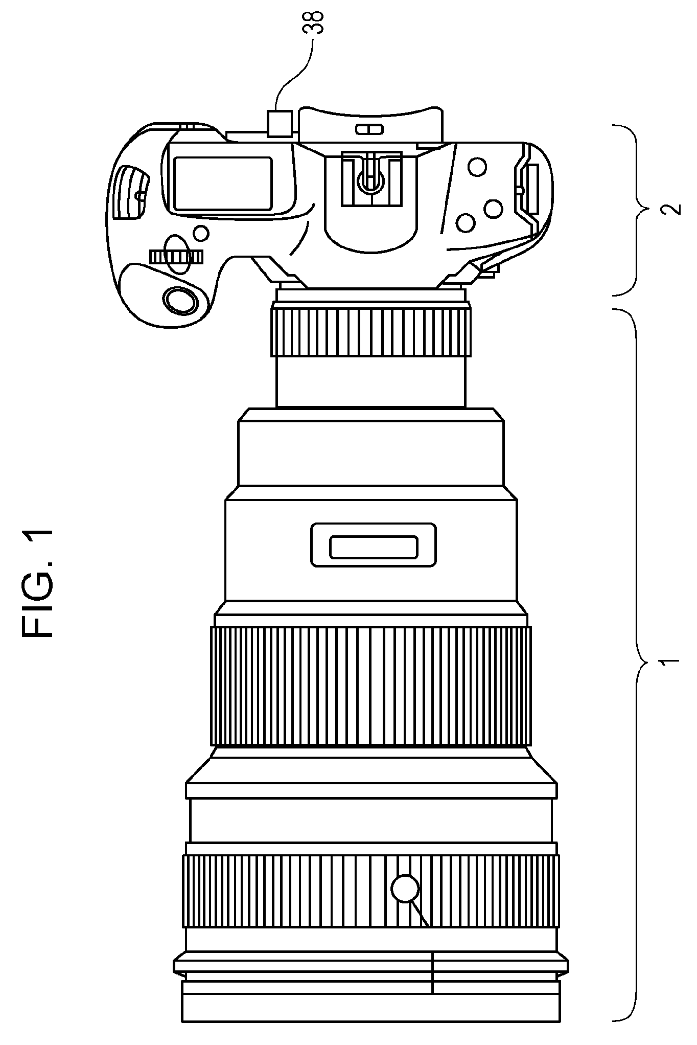
[0072]FIG. 1 is a diagram showing the configuration of a camera serving an image capturing apparatus according to a first embodiment of the present invention.

[0073]The camera in FIG. 1 has the function of capturing a moving image and a still image. Reference sign 1 denotes a lens barrel including an image-blur correction apparatus, and reference sign 2 denotes a camera body including an image sensor 36 (a photoelectric transducer or the like).

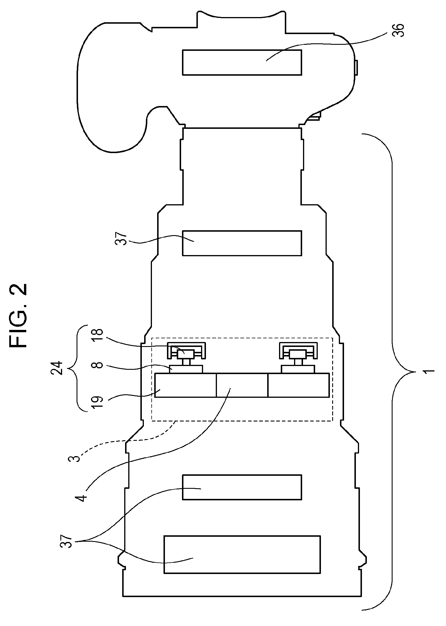
[0074]FIG. 2 is a schematic diagram illustrating the interior of the lens barrel 1 and the camera body 2.

[0075]In FIG. 2, reference sign 3 denotes the image-blur correction apparatus.

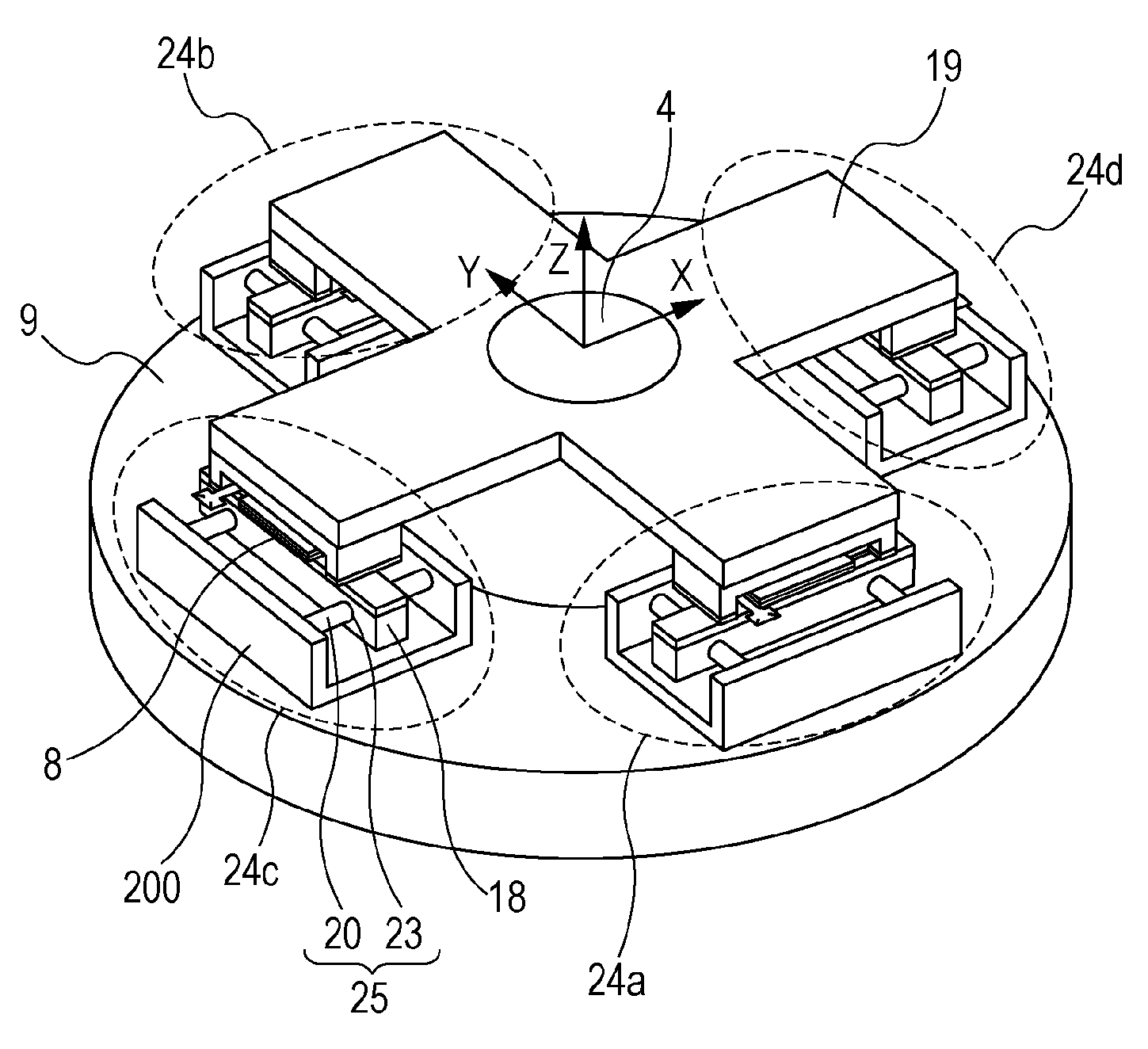
[0076]Reference sign 4 denotes an optical lens and reference sign 24 denotes a vibration-type driving unit. Reference sign 19 denotes a moving body, to which the optical lens 4 is mounted in this example.

[0077]Reference sign 18 denotes a contact member, which is in pressure-contact with a vibrator 8. By causing the vibrator 8 to vibrate in an elli...

second embodiment

[Second Embodiment]

[0159]Next, a second embodiment will be described. The difference between the second embodiment and the first embodiment is the configuration of the moving mechanism 25.

[0160]The configuration of the difference from the first embodiment will be described hereinbelow.

[0161]FIG. 11 is a perspective view of a vibration-type driving unit 24 used in an image capturing apparatus of the second embodiment.

[0162]The X-direction in FIG. 11 is the driving direction (the first direction) of the vibration-type driving unit 24.

[0163]The Y-direction is the deflecting direction (the second direction) in which the moving body 19 and the support member 200 can be moved relative to each other by the moving mechanism 25.

[0164]The moving mechanism 25 is formed of two rectangular thin plate-like elastic members made of stainless steel. The thickness direction thereof is the Y-direction (the deflecting direction or the second direction).

[0165]One end is bent at a right angle by press wo...

third embodiment

[Third Embodiment]

[0180]Next, a third embodiment will be described. The difference between the third embodiment and the first embodiment is the configuration of the moving mechanism 25.

[0181]The configuration of the difference from the first embodiment will be described hereinbelow.

[0182]FIG. 12A is a perspective view of the configuration of a vibration-type driving unit 24 of the third embodiment. FIG. 12B is a top view, and FIG. 12C is a side view.

[0183]The X-direction in FIGS. 12A to 12C is the driving direction (the first direction) of the vibration-type driving unit 24. The Y-direction is the deflecting direction (the second direction) in which the moving body 19 and the support member 200 can be moved relative to each other by the moving mechanism 25.

[0184]The contact member 18 includes the abrasion-resistant member 22, the contact-member main body 21 made of a neodymium magnet, and the contact-member transmitting portions 23.

[0185]The moving mechanism 25 includes the contact-...


PUM


Abstract

A vibration-type driving unit includes a vibrator including an electro-mechanical transducer; a moving body provided with the vibrator; a contact member in contact with the vibrator provided on the moving body; a support member configured to support the contact member; and a moving mechanism configured to move the moving body relative to the support member. The vibrator and the contact member are disposed so that the vibrator moves in a first direction relative to the contact member. The moving mechanism is configured to move the moving body relative to the support member in a second direction intersecting the first direction in a plane parallel to a plane in which the vibrator and the contact member are in contact with each other.

Description

BACKGROUND OF THE INVENTION[0001]1. Field of the Invention[0002]The present invention relaters to a vibration-type driving unit, as well as a two-dimensional driving apparatus, an image-blur correction apparatus, an interchangeable lens, an image capturing apparatus, or an automatic stage including the vibration-type driving unit.[0003]2. Description of the Related Art[0004]Great many vibration-type driving units that excite vibrations in a vibrator to move a moving body that is in pressure-contact therewith have been proposed.[0005]They are positioned as important functional components particularly in optical devices which are required to operate accurately. An example thereof is a two-dimensional driving apparatus including a plurality of linear vibration-type driving units (a type capable of linearly moving a moving body), in which the driving operations thereof are combined, allowing two-dimensional movement of the moving body.[0006]Another known example is an image-blur correct...

Claims


Application Information

Patent Timeline
Patent Type & Authority Patents(United States)
IPC IPC(8): H04N5/232H02N2/00H02N2/10H02N2/02
CPCH04N5/23287H02N2/004H02N2/0055H02N2/0095H02N2/026H02N2/028H02N2/103H02N2/108H04N5/2328G03B2205/0061G03B5/02G03B17/14G03B2205/0015H02N2/0015H04N23/685H04N23/687
Inventor OHASHI, KAISHI
Owner CANON KK
Why Eureka
Try Eureka