Method and system for treatment of visual impairment

a visual impairment and treatment method technology, applied in the field of ophthalmology, can solve the problems of partial or full paralysis of the non-leading eye, misalignment between the eyes, and the normal way the human eye stares at objects in the normal way,

Active Publication Date: 2016-02-09
NOVASIGHT LTD
View PDF10 Cites 3 Cited by
  • Summary
  • Abstract
  • Description
  • Claims
  • Application Information

AI Technical Summary

Benefits of technology

[0052]The other object of the invention is to provide a new and improved method and system for treatment of visual impairment which can be implemented as a compact, light and convenient eyewear.
[0053]Another object of the invention is to provide a new and improved method and system for treatment of visual impairment which enables reliable eye tracking with a speed corresponding to the speed of eye movements.
[0054]Yet another object of the invention is to provide a new and improved method and system for treatment of visual impairment which enables producing a good quality image with required resolution and displaying this image without distortion before a non-leading eye.
[0063]The main idea lying behind the present invention is to employ a miniature, wide angle digital video camera which can be still and don't require mechanical displacement for obtaining the whole image of a scene seen by the leading eye. The camera will be electronically producing virtual image of the scene and then delivering this image after it has been electronically processed to the non-leading eye. Such a camera is capable to electronically scan the entire required field of view. The scanning can be done reliably and with a speed corresponding to velocities of the eye movements. Since the camera is miniature the whole system can be implemented for example as a compact eyewear conveniently worn by a patient.
[0066]The other feature employed in the present invention is using of a miniature image producing device and placing the image producing device in close proximity to at least one of the eyes. By virtue of this provision the image sent to the display device may have high resolution since there is no need in a cumbersome bundle of fiber optics to relay the image.

Problems solved by technology

The normal way the human eyes stare at an object is rather complicated.
Such pathologies may result in the so-called strabismus, i.e. a condition in which one eye is not able to stare at the same direction in space as the other eye and hence there exists misalignment between both eyes.
Paralytic strabismus, with all its derivatives, is a kind of visual impairment in which some or all the extra ocular muscles are partially or fully non operative, resulting in partial or full paralysis of the non-leading eye.
In a more severe situation, all those problems can occur in both eyes.
In the developing child this can prevent the proper development of vision in the affected eye resulting in amblyopia.
Some adults are also able to suppress their diplopia, but their suppression is rarely as deep or as effective and takes longer to establish.
Thus, many of those people having double vision suffer from blurred vision, eyes pain, headache, nausea, balance problems and more.
This is associated with deterioration of depth perception.
This idea however was never implemented as a real commercially available apparatus suitable for persons suffering from various kinds of strabismus.
Since eye movements are very rapid, the image produced by mechanically swiveled camera will lag behind the fast movement of the leading eye and therefore instead of real image a non realistic transient image would be produced by the camera and the real image seen by the leading eye and the lagging image produced by the mechanically driven camera would not be able to be integrated by the brain.b. Mechanically swiveled video camera is cumbersome and heavy: it is complicated, expensive and needs maintenance.c. Mechanical systems in general and mechanically swiveled cameras in particular require higher energy for their operation and thus heavier batteries.d.
This solution is cumbersome and does not allow to achieve high resolution image since the number of light conducting strands (fiber optics) in the bundle is limited.
The required number of pixels for a good quality image is in the range of millions; however fiber optics bundle consisting of millions strands would be impractical.
Due to the mentioned above reasons the Lamprecht's solution resulted in a big, heavy and cumbersome apparatus, designed as a helmet.
Nevertheless, even though such helmet apparatus could be feasible, it would be not practical for everyday use and will not allow sufficient resolution for obtaining good quality image since a resolution provided by light conducting cable is limited.
In conclusion one could state that even though the Lamprecht's idea has been devised as early as in 1994, the long felt problem of impaired vision associated with the eyes misalignment still remains unsolved and requires proper solution.

Method used


Image

  • Method and system for treatment of visual impairment
  • Method and system for treatment of visual impairment
  • Method and system for treatment of visual impairment

Examples


case # 1

[0109]Case #1:

[0110]The case refers to a situation when a patient's left eye is the leading eye and patient's right eye is the non-leading eye. The non-leading eye still is able to perform some limited movements.

[0111]In FIG. 8 configuration of the system is shown as a block diagram. The block diagram suitable for this case includes those components which have been already mentioned above in connection with FIGS. 6a, 6b.

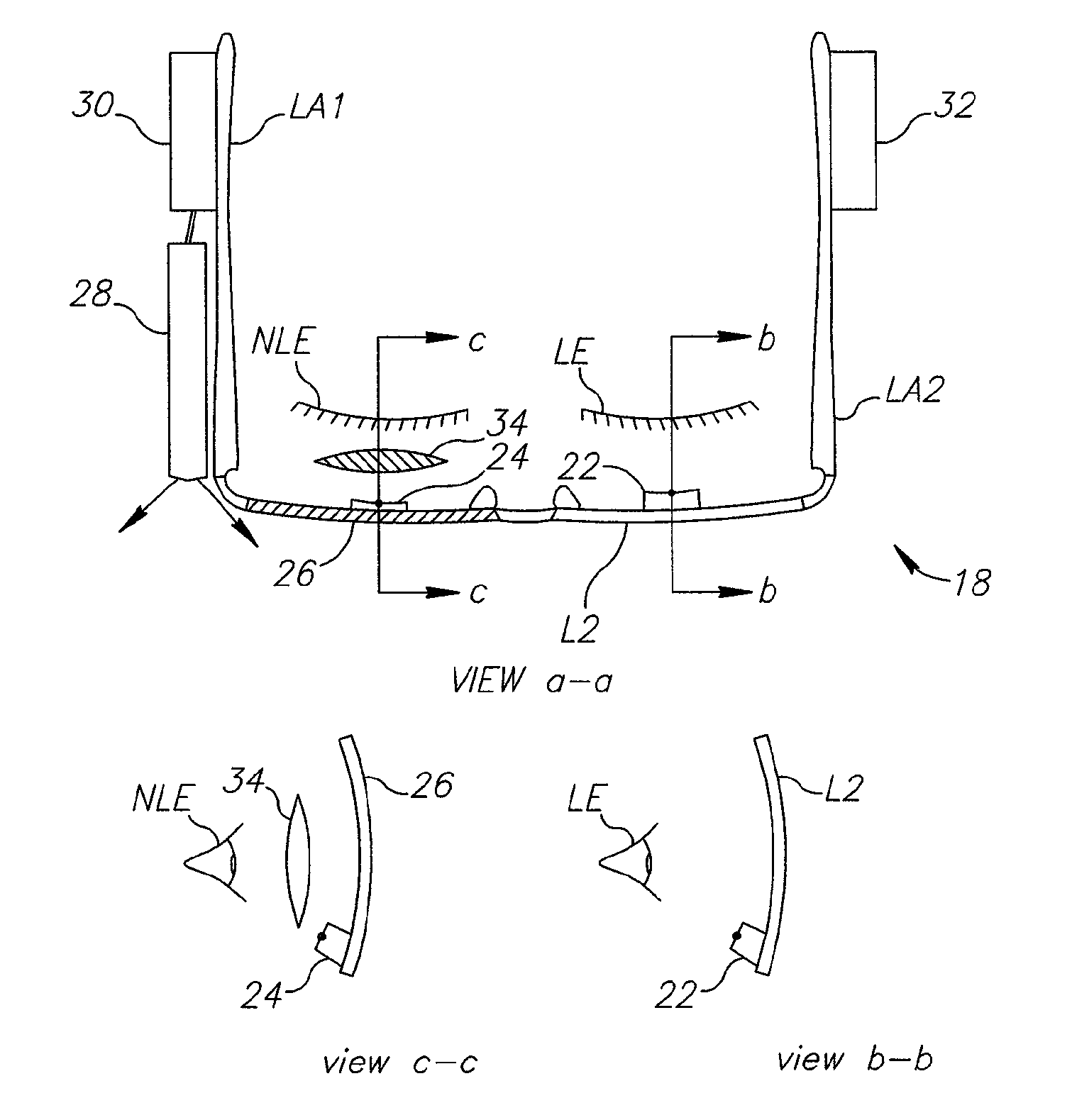
[0112]It is seen that lens L2 is located in front of leading eye LE. The lens L2 is a conventional lens. If the leading eye has no focusing problem, the diopter number prescribed for that lens can be zero. In all other cases, the diopter number of the leading eye lens L2 can be prescribed by optometrist. Through this lens, the patient leading eye has an unobstructed view of the scene such that it can see for example an object 38 in front of it.

[0113]First eye tracker 24 is located in the lower portion of the leading eye lens L2 so as not to obscure the leading eye v...

case # 2

[0120]Case #2:

[0121]This case refers to a situation when patient's left eye is the leading eye and the right eye is the non-leading eye and the non-leading eye has full paralysis.

[0122]The block diagram of the system suitable for treatment of this case would be basically the same as seen in FIG. 8. However, in this case the second eye tracker would not be required since the non-leading eye is fully immobile due to paralysis and its direction is fixed with reference to the head's direction. Accordingly the gazing angle α of the non-leading eye is known in advance and it can be taken into consideration in all calculations necessary for correcting angular deviation between leading eye and non-leading eye.

case # 3

[0123]Case #3:

[0124]This case addresses to a situation when both eyes of the patient gaze in abnormal directions (i.e. alternating strabismus, nystagmus etc.).

[0125]The block diagram of the system is shown in FIG. 9. It can be easily seen that it is basically similar to the system presented on diagram seen in FIG. 8.

[0126]Accordingly the similar components are designated by similar reference numerals. However, configuration of the system suitable for treatment of this case would require an additional video camera 40 positioned near the leading eye and an additional wide angle display device 39 positioned in front of the leading eye.

[0127]An additional eyepiece lens 42 could be provided in front of the leading eye.

[0128]It is designated by straight lines the directions of virtual view between cameras and the object, as well as the directions of required view between the eyes and the object.

[0129]A non-limiting table below summarizes the possible hardware configurations of the system ...


PUM


Abstract

Method and system for treating of visual impairment associated with misalignment between eyes of a patient is described. The invention allows to obtain electronically of an image of an object at which one eye of the patient is staring, calculating angular deviation between staring direction of this eye and the second eye and displaying before the second eye the image after it has been electronically processed so as to correct the angular deviation and to obtain the image, which would be perceptible by the brain as a single three dimensional stereoscopic image.

Description

FIELD OF THE INVENTION[0001]The present invention relates to ophthalmology and more specifically to treatment of visual impairment caused by a condition in which eyes of a patient are not properly aligned such that the gaze of each eye is not directed to the same point in space, thus preventing proper binocular vision.[0002]More particularly the present invention concerns a method and a system for treatment of visual impairment associated with pathologies of the extra ocular eye muscles or with other problems causing a phenomenon known as diplopia (Double Vision). One of pathologies causing diplopia is known as strabismus. It should be borne in mind however, that the present invention is not limited merely to treatment of strabismus and it can be used also for treatment of other kinds of visual impairment associated with diplopia. One should also bear in mind that the present invention can be used not merely for therapeutic treatment per se but also for training and / or rehabilitatio...

Claims


Application Information

Patent Timeline
Patent Type & Authority Patents(United States)
IPC IPC(8): A61B3/08A61B3/113G02B27/01G02B27/22A61B3/14A61B3/00G06K9/00
CPCA61B3/0025A61B3/113G02B27/017G02B27/225G06K9/00604G02B2027/0138G02B2027/0178G02B2027/0187A61B3/085G06V40/19A61B3/08
Inventor OZ, DAN
Owner NOVASIGHT LTD
Why Eureka
Try Eureka