Insulating and venting assembly

a technology of venting assembly and insulation, which is applied in the direction of ventilation system, lighting and heating apparatus, heating type, etc., can solve the problems of ineffective moisture venting, ineffective moisture venting, and ineffective radiant barrier surface loss of a considerable amount, if not all, of radiant barrier ability to reflect back. , to achieve the effect of economic and effective moisture venting

Inactive Publication Date: 2016-02-09
MCCARY SR JOHN MILNER
View PDF19 Cites 7 Cited by
  • Summary
  • Abstract
  • Description
  • Claims
  • Application Information

AI Technical Summary

Benefits of technology

[0012]Briefly described, the present invention comprises an economical and effective heat and cold insulating and venting assembly including structural insulating style panels (SIPS) and nail base style insulation assemblies that can also assist in insulating the structure from radiation heat transfer through walls, roofs or in other radiant barrier applications. The insulating and venting assembly's unique configuration either keeps radiant heat from penetrating through the roof or wall, or vents out the conduction generated heat. The SIP and nail base insulation assemblies' configurations can also be very effective in moisture venting.

Problems solved by technology

Improper venting and moisture control can impact the ability of the wall or roof system to control heat (insulation saturation with moisture and collapse) and to maintain the structural integrity of the building (rot, decay, or insects).
But most of the radiant reflective insulation on the market today does not address one of the major requirements for an effective radiant barrier.
One of the problems or inefficiencies of many of the radiant barrier applications is that when reflective surfaces of the foil engage another surface, such as the fiberglass of an adjacent insulation blanket or the adjacent gypsum foam board or other wall structure, such as siding, the radiant barrier surface loses a considerable amount, if not all, of the radiant barriers ability reflect back or not radiate radiant heat (effective low emissivity).
Another problem with the use a radiant barrier surface on combination with other insulation materials is that the surface should become dirty from an accumulation of dust, trash, fibers, vapors, etc., the reflective sheet loses its ability to reflect back or not emit radiant heat.

Method used


Image

  • Insulating and venting assembly
  • Insulating and venting assembly
  • Insulating and venting assembly

Examples


Embodiment Construction

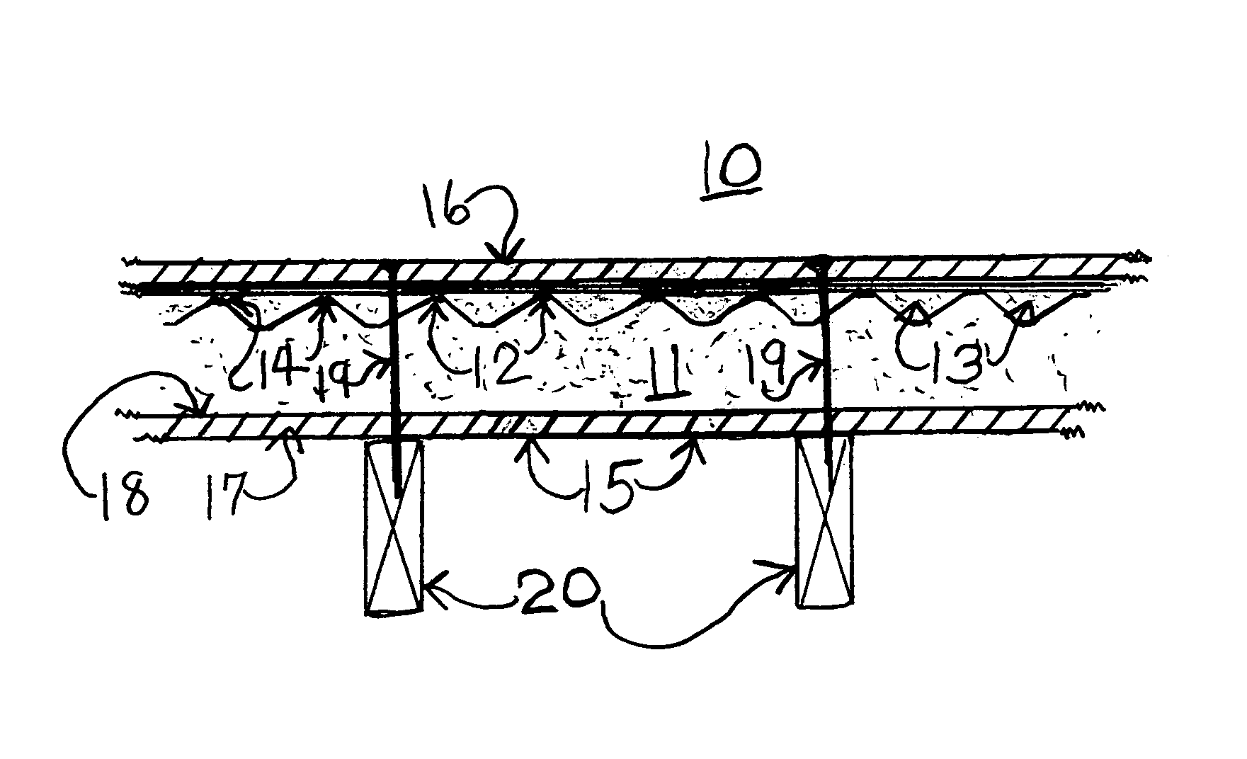
[0023]Shown in FIG. 1 in a cross sectional view is the radiant insulating and venting assembly 10 components used in a new roofing application. Shown is a rigid foam sheet 11 with the non-collapsing air spacer columns 12 and air spaces 13 between the air spacers. The outer ends of the air spacers 14 can be are attached to the radiant barrier low emissivity surface 15. The radiant barrier low emissivity surface 15 is adhered to the upper rigid board 16, or the low emissivity surface 15 can be adhered to the surface of the air spaces 13. A low emissivity surface 15 can also be attached to the lower face of the lower rigid board 17, that is attached to the lower face 18 of the rigid foam sheet 11. Nails, screws or other attaching mechanisms 19 adheres the insulating and venting assembly 10 to the roof rafters 20. Air and moisture flows 21 up through the air spaces 13.

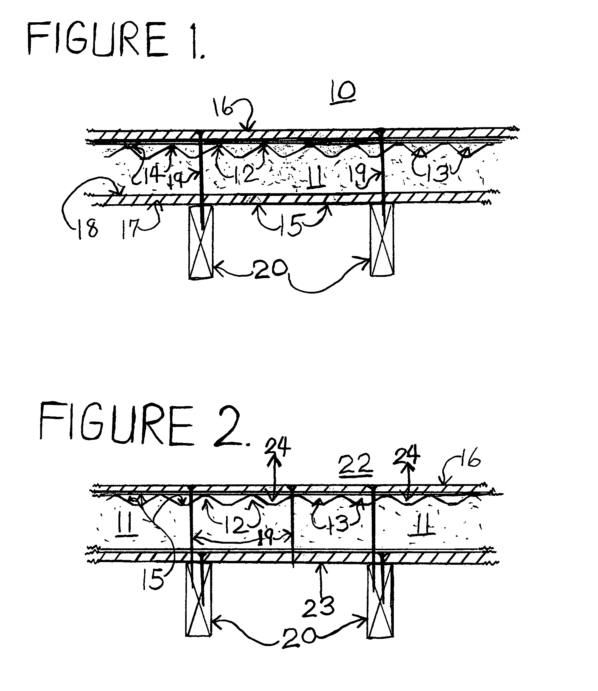
[0024]FIG. 2 shows in a cross sectional view the insulating and venting assembly 22 used in a re-roofing or retrofit roo...


PUM


Abstract

The present invention comprises an effective insulation and ventilating assembly that can insulate a structure, usually in roofing or exterior wall applications, from conductive, convective and radiant heat. The insulating and venting assembly is comprised of a rigid foam sheet and a rigid panel such as oriented strand board (OSB) or plywood attached one or both sides of the rigid foam sheet. The rigid foam sheet has air spacer columns and air spaces on one or both faces. Radiant barrier layers can be applied to either faces of the rigid panels and/or can be applied to the air spacer and air space surfaces allowing for radiant heat to be radiating back or radiant heat to not be reradiated by the radiant barrier low emissivity surface. The air spaces in the rigid foam face allows air and moisture to be vented though the insulating and venting assembly.

Description

CROSS-REFERENCED TO RELATED APPLICATIONS[0001]This application makes reference to U.S. Pat. No. 8,291,660 and U.S. Pat. No. 8,635,823.BACKGROUND OF THE INVENTION[0002]Roofs and walls of a building or structure must deal with various environmental and interior building factors such as heat and cold insulation, proper venting and moisture control. The design of the roof and wall systems needs to be structurally sound while providing for a habitable temperature living space. Structural Insulating Panels or SIPS and nail base panels have been used in building's roof and wall construction for many years. Customarily SIPS are constructed by having rigid foam insulation board sandwiched between plywood and oriented strand board (OSB) panels. Nail base panels are usually constructed with plywood or OSB adhered to just one side of rigid foam. Traditional SIPS are used in new building construction and nail base panels used in retrofit or remodeling structures. The rigid foam give heat and col...

Claims


Application Information

Patent Timeline
Patent Type & Authority Patents(United States)
IPC IPC(8): E04B1/70E04D13/17E04B1/80E04B1/76E04C2/34E04D13/16
CPCE04D13/1618E04B1/7612E04D13/172E04B1/80E04C2/34E04B1/7069E04B1/74E04C2/296E04B2001/7691
Inventor MCCARY, SR., JOHN, MILNER
Owner MCCARY SR JOHN MILNER
Why Eureka
Try Eureka