Cutter apparatus for centrifugal pump

a centrifugal pump and cutter technology, applied in specific fluid pumps, non-positive displacement pumps, fluid engines, etc., can solve the problems of homa assembly operation flaws, clogging of manure slurry and municipal waste markets, and clogging of clogging

Active Publication Date: 2016-02-09
CORNELL PUMP CO LLC
View PDF14 Cites 2 Cited by
  • Summary
  • Abstract
  • Description
  • Claims
  • Application Information

AI Technical Summary

Problems solved by technology

Pumps in both the manure slurry and municipal waste markets are subject to clogging due to the nature of stringy materials and other soft solids which tend to restrict or block the impeller passages in a centrifugal pump.
This clogging can occur as often as every few days.
The Homa assembly has operational flaws, including shortcomings present in any welded device designed without thought to hydraulic impact of the cutters.
For example, the Homa cutter and stator teeth block flow into the impeller, causing substantial pressure drop as flow enters the pump.
This pressure drop will limit the amount of “lift” that the pumps can generate, limit the flow range of a pump, limit the size of a solid that can flow through the pump, and increase the amount of power that would be required to operate the pump.
The cutter teeth and impeller will have a reduced operational life because of the unbalance.
Welding the teeth adds problem on operation of the pump.
For example, welds can be attacked by corrosion causing premature failure.
Heating from the welds can damage the impeller and stator.
That is, the heat could warp the teeth and change the base structure of the underlying material.
In addition, impact loads (from cutting) are concentrated at the weld points leading to reduced impeller / stator life.
Further, the welded on teeth are non-replaceable.
This means that failure at the weld would likely require a new impeller or plate in order to make a repair that now requires a pump rebuild.
Even prior to failure, the welded-on teeth are wear items and will need to be renewed on a regular basis.
Since pumps can go several years without a major rebuild, the requirement that base parts (impeller / stator) be replaced with the teeth is an expensive time consuming problem for pump users.

Method used


Image

  • Cutter apparatus for centrifugal pump
  • Cutter apparatus for centrifugal pump
  • Cutter apparatus for centrifugal pump

Examples


Embodiment Construction

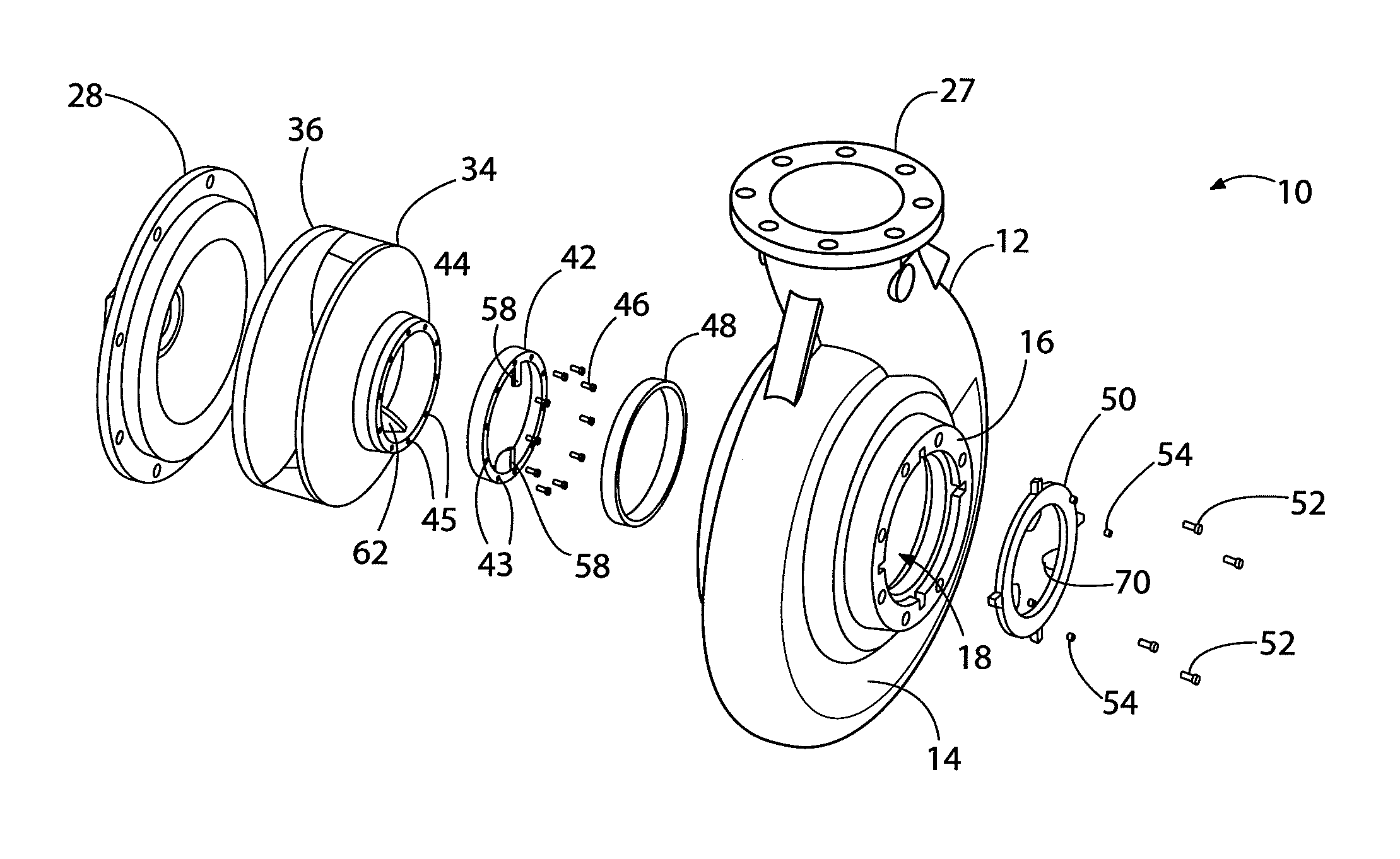
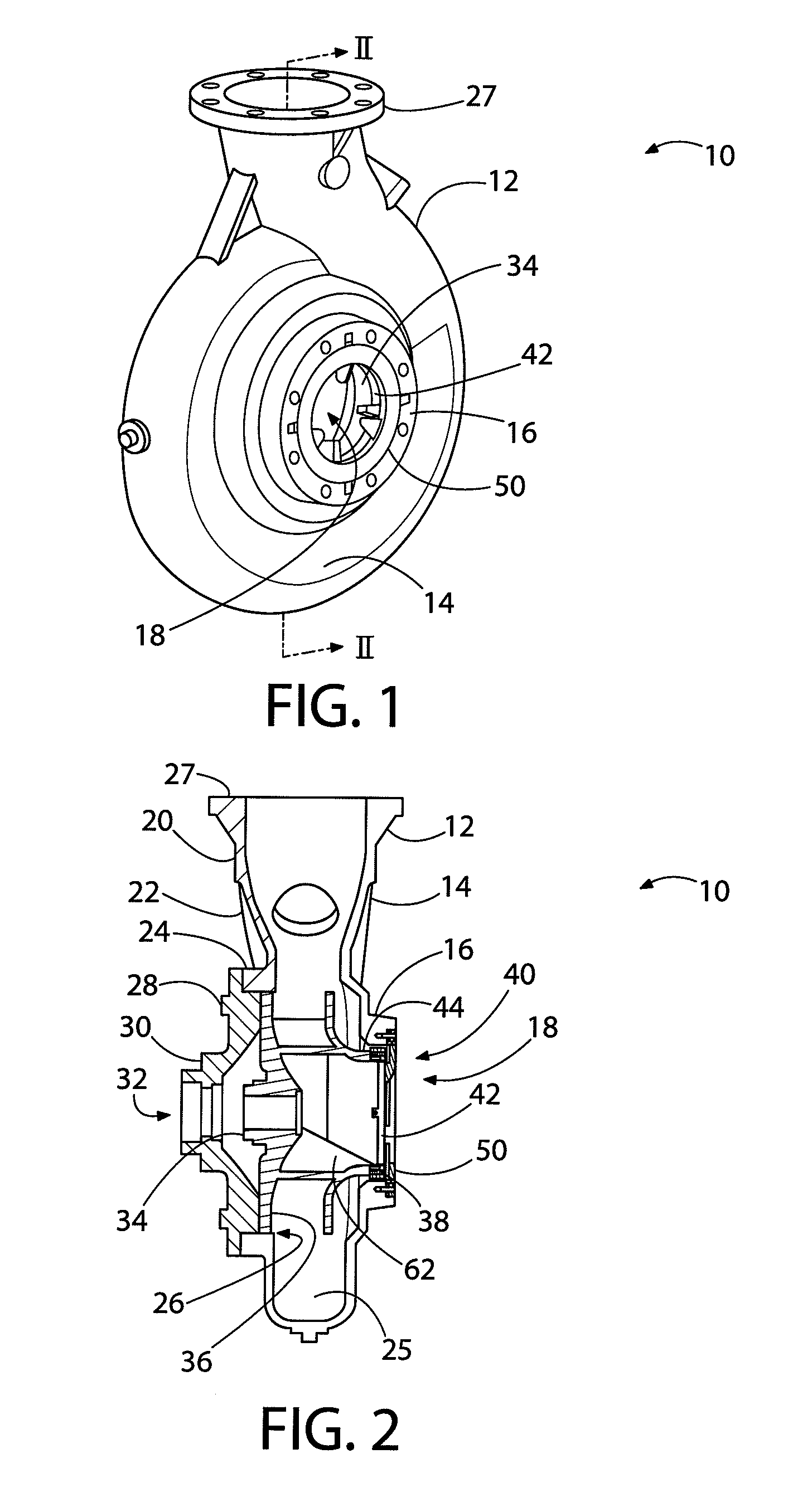
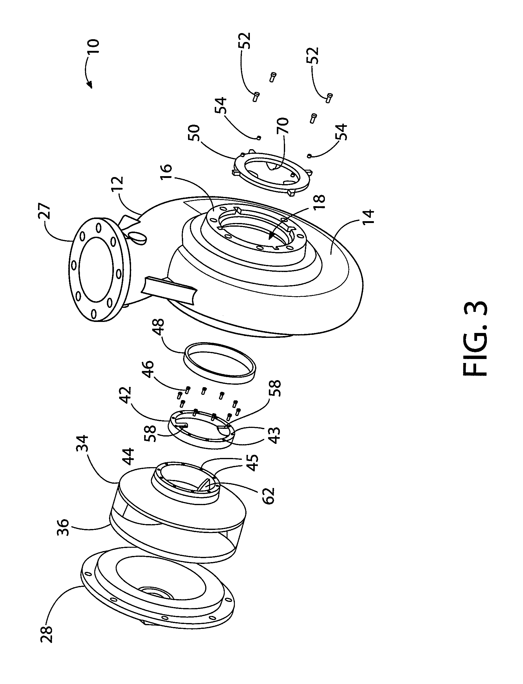
[0023]The examples of the invention shear apart solids in a centrifugal pump's suction inlet to prevent restriction or blockage in the impeller passages. The shearing action is accomplished by the mechanical interaction of a cutter ring fastened to the rotating impeller and a cutter plate fastened to the stationary volute of the centrifugal pump. The action of the cutter mechanism disrupts the formation of the clogging action and keeps flow moving through the pump. Some elements of the exemplary embodiments may include: profiled cutter teeth to optimize flow and Net Positive Suction Head (NPSH) characteristics, adjustable cutter clearances to maintain optimal shearing action, keyed engagement that takes impact away from the fasteners on a rotating cutter ring and stationary cutter plate. Further, the exemplary embodiments may be retrofitable to current solids handling pumps.

[0024]The exemplary embodiments include cutter and stator teeth that minimize clogging of the impeller passage...


PUM


Abstract

A centrifugal pump with a cutter mechanism consisting of a toothed cutter rotor, integral with the impeller wear ring, affixed to the impeller and a toothed cutter stator affixed to the casing, separately from the casing wear ring. A cutter mechanism consisting of a stator and rotor set such that they may be installed on the centrifugal pump impeller and casing as original equipment or as a retrofit. A cutter mechanism such that when installed in a centrifugal pump they prevent stringy materials, garbage and other agglomerated soft wastewater solids from partially restricting or totally blocking the inlet to the pump impeller. A cutter mechanism such that when it prevents solids from restricting or blocking the impeller inlet, it does so without significant decrease of flow throughput or significant increase in absorbed hydraulic horsepower.

Description

BACKGROUND OF THE INVENTION[0001]1. Field of Invention[0002]This invention relates generally to pumps for liquids, and more particularly, to centrifugal pump cutters for cutting solids suspended in the liquid.[0003]2. Description of Related Art[0004]Pumps in both the manure slurry and municipal waste markets are subject to clogging due to the nature of stringy materials and other soft solids which tend to restrict or block the impeller passages in a centrifugal pump. This clogging can occur as often as every few days.[0005]One attempt to solve the clogging problem was provided by a drawing of an “A Series Cutter Assembly: Drawing #046897” to Homa. The Homa assembly is a crude welded device with a single slicer blade welded to a cutter plate, and two flat slicer blades welded inside an impeller and leaving a small opening therebetween. The Homa assembly has operational flaws, including shortcomings present in any welded device designed without thought to hydraulic impact of the cutte...

Claims


Application Information

Patent Timeline
Patent Type & Authority Patents(United States)
IPC IPC(8): F04D7/04
CPCF04D7/045
Inventor ADAMS, JOHN D.TIMMONS, FRANK D.GARVIN, JAMES C.SCHOENBRUN, STEVE J.
Owner CORNELL PUMP CO LLC
Why Eureka
Try Eureka