
Temperature sensor and method for measuring a temperature change

a temperature sensor and temperature technology, applied in the direction of interferometric spectrometry, instruments, optical radiation measurement, etc., can solve the problems of sensor without appreciable self-heating and unproven milli-kelvin measurement accuracy, and achieve high-quality and stable temperature measurement.

Active Publication Date: 2016-02-09
CARL ZEISS SMT GMBH
View PDF42 Cites 0 Cited by
  • Summary
  • Abstract
  • Description
  • Claims
  • Application Information

AI Technical Summary

Benefits of technology

The invention is a temperature sensor that can accurately measure temperature changes in the long term, regardless of environmental conditions such as pressure and airflows. It uses optical waveguides that have different temperature dependencies, which helps to improve accuracy. Additionally, using multiple optical waveguides with different temperature dependencies can further increase accuracy.

Problems solved by technology

However, these platinum temperature sensors drift with several milli-Kelvin per year and react, moreover, to changes to the flow speed of the air surrounding them due to their self-heating.
Sensors without any appreciable self-heating, e.g. capacitive length measuring systems, have not until now been able to demonstrate milli-Kelvin measuring accuracy.

Method used


Image

  • Temperature sensor and method for measuring a temperature change
  • Temperature sensor and method for measuring a temperature change
  • Temperature sensor and method for measuring a temperature change

Examples


Embodiment Construction

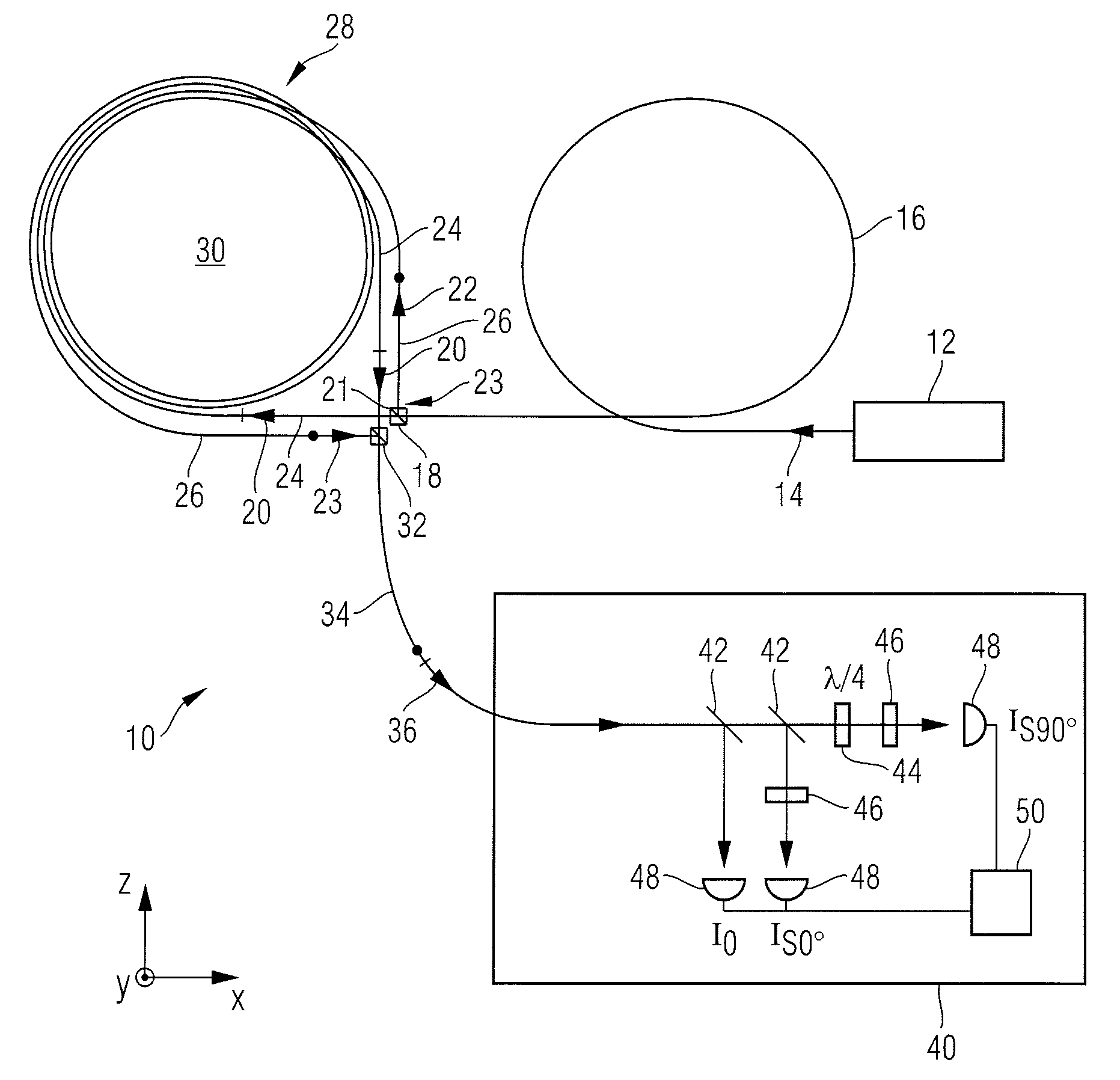
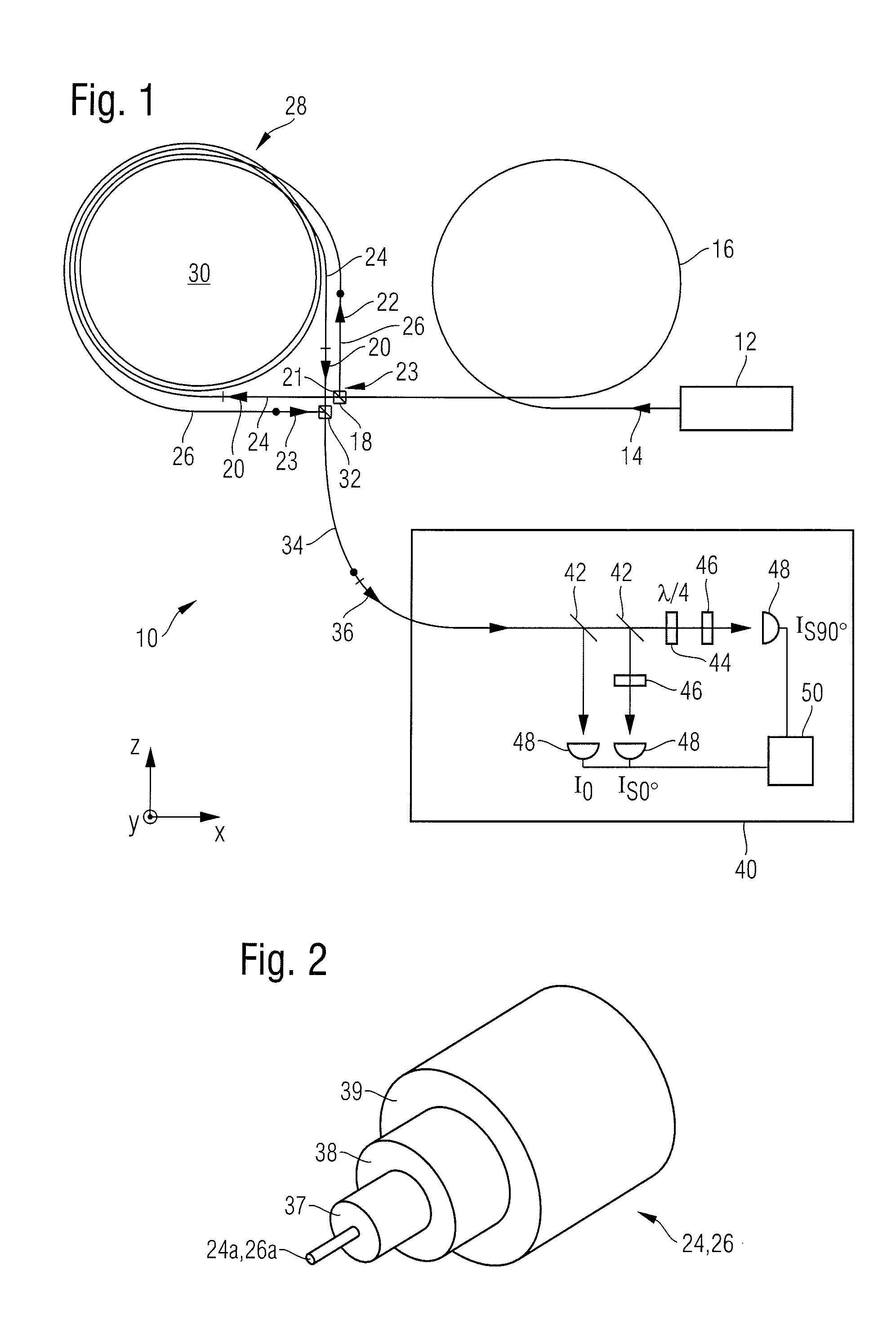
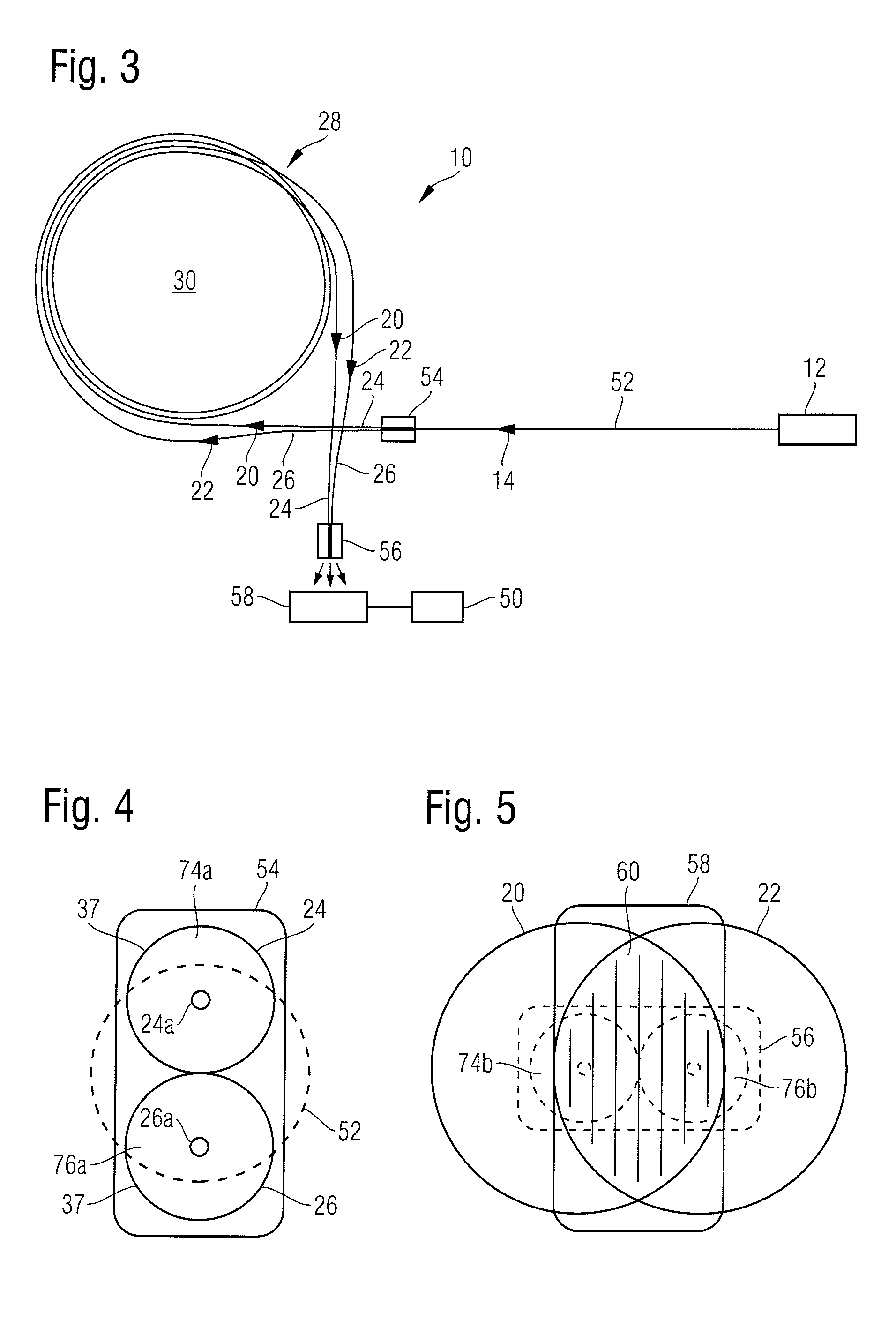
[0038]In the exemplary embodiments and embodiments described below, elements which are similar to one another functionally or structurally are provided as far as possible with the same or similar reference numbers. There, in order to understand the features of the individual elements of a specific exemplary embodiment one should refer to the description of other exemplary embodiments or to the general description of the invention.

[0039]In order to facilitate the description of the projection exposure tool there is specified in the drawing a Cartesian xyz coordinate system which gives the respective relative position of the components shown in the figures. In FIG. 1 the y direction runs out of the plane of the drawing perpendicular to the latter, the x direction to the right, and the z direction upwards.

[0040]FIG. 1 illustrates an embodiment according to the invention of a temperature sensor 10 for measuring a temperature change in a medium, e.g. in air. The temperature sensor 10 com...


PUM

PropertyMeasurementUnit
lengthaaaaaaaaaa
lengthaaaaaaaaaa
lengthaaaaaaaaaa

Abstract

A temperature sensor is provided which comprises a measurement light source for generating measurement light and two optical waveguides. The two optical waveguides are arranged such that they respectively receive a measurement light portion of the measurement light and that the measurement light portions are superimposed after passing through the optical waveguides. Furthermore, the two optical waveguides have an optical property with different temperature dependency.

Description

CROSS-REFERENCE TO RELATED APPLICATION[0001]This application claims priority to German Patent Application 10 2012 006 420.9, filed on Mar. 30, 2012. The entire disclosure of the above application is herein incorporated by reference.BACKGROUND[0002]The invention relates to a temperature sensor, a method for measuring a temperature change and a mask inspection apparatus for inspecting a lithography mask with this type of temperature sensor.[0003]For highly accurate determination of the temperature of air for example with milli-Kelvin precision or better, in the prior art platinum temperature sensors are used. These platinum temperature sensors are used, for example, to stabilise the temperature in the region of the mask table of a mask inspection apparatus which is used for the inspection of a lithography mask. However, these platinum temperature sensors drift with several milli-Kelvin per year and react, moreover, to changes to the flow speed of the air surrounding them due to their ...

Claims


Application Information

Patent Timeline
Patent Type & Authority Patents(United States)
IPC IPC(8): G01K11/32G01J3/45G01J5/00G01N21/17
CPCG01N21/171G01K11/32
Inventor SCHNIER, DIETMAR
Owner CARL ZEISS SMT GMBH
Learn More