Aeroengine fuel nozzle coking test device and heat flow measurement method

A technology for aero-engines and fuel nozzles, which is applied in the direction of engine components, machines/engines, jet propulsion devices, etc. It can solve the problems of testing the coking properties of fuel nozzles, and achieve the effect of benefiting from the complexity of nozzle coking, convenient replacement and low price

Active Publication Date: 2019-08-06
HARBIN INST OF TECH
View PDF7 Cites 0 Cited by
  • Summary
  • Abstract
  • Description
  • Claims
  • Application Information

AI Technical Summary

Problems solved by technology

[0005] The purpose of the present invention is to solve the problem that there is no special test device for testing the coking properties of fuel nozzles, and to provide a coking test device for fuel nozzles of aero-engines and a heat flow measurement method

Method used


Image

  • Aeroengine fuel nozzle coking test device and heat flow measurement method
  • Aeroengine fuel nozzle coking test device and heat flow measurement method
  • Aeroengine fuel nozzle coking test device and heat flow measurement method

Examples


specific Embodiment approach 1

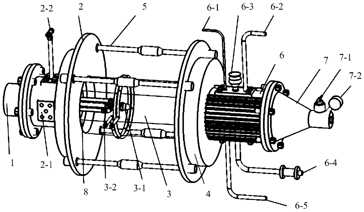
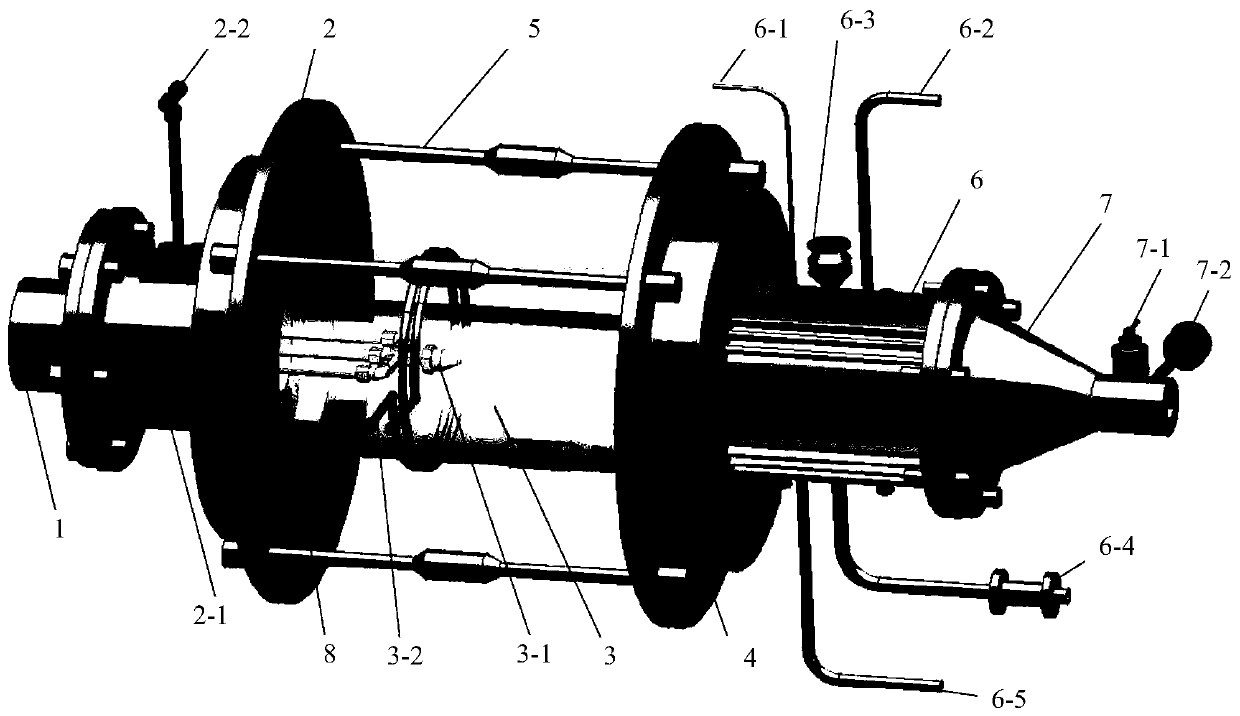
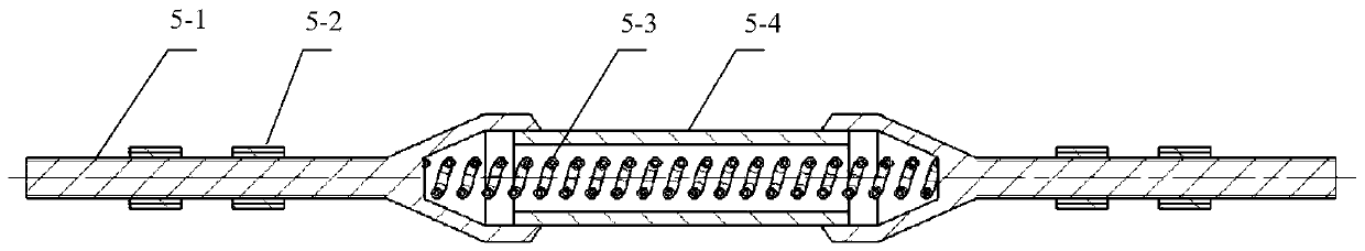
[0021] Specific implementation mode 1: the following combination Figure 1 to Figure 3 Explaining this embodiment, the aero engine fuel nozzle coking test device of this embodiment includes an intake pipe 1, a front support plate 2, a quartz cavity 3, a rear support plate 4, a plurality of thermal deformation buffers 5, a radiating cylinder 6, and Tailpipe 7,

[0022] The outer convex port of the intake pipe 1 and the front support plate 2 is connected by a flange. The quartz cavity 3 is clamped between the front support plate 2 and the rear support plate 4, and the front support plate 2 and the rear support plate 4 pass through Two thermal deformation buffers 5 are connected, one end of the radiating cylinder 6 is connected to the rear support plate 4, and the other end is connected to the head end of the tail pipe 7 through a flange; the intake pipe 1, the front support plate 2, the quartz cavity 3, the heat dissipation The cylinder 6 and the tail pipe 7 form a communicating c...

specific Embodiment approach 2

[0049] Specific implementation manner 2: The thermal flow measurement method of the aero engine fuel nozzle of this embodiment is implemented based on the above-mentioned aero engine fuel nozzle coking test device,

[0050] Since the nozzle is in the process of working, in addition to the aerodynamic heating and heat transfer of the incoming air flow, there is also radiation heat transfer from the combustion of the combustion chamber, which has the characteristics of high heat flux. The method of the present invention uses electromagnetic induction heaters for heating. It can provide the heating demand of the high heat flux density of the small structure of the nozzle mouth, and at the same time, ensure that the heater does not contact the nozzle, so as to avoid the impact or pollution on the coking. The calibration method of temperature measurement and heat exchange on the nozzle surface by infrared thermal imaging camera is as follows:

[0051] In the absence of oil, the electrom...


PUM


Abstract

The invention relates to an aeroengine fuel nozzle coking test device and a heat flow measurement method, belonging to the technical field of nozzle performance test. The invention aims at solving theproblem that a special test device is not available for testing the coking property of a fuel nozzle. A gas inlet system can provide different types of gases with certain pressure, temperature and flow rate; a measurement and control system can perform immediate feedback, recording and control on test parameters; a heating system has an ability to provide rapid heating of small structures with ahigh heat flux density; a back pressure system provides a stable working environment for the nozzle in a specific environment; a nozzle system simulates the fuel supply of an actual research object; avisualization system can meet the demands of a charge coupled device (CCD) high-speed camera needed by a test, the distribution of particles and other products, and the use of optical diagnostic testequipment such as PIV. The aeroengine fuel nozzle coking test device and the heat flow measurement method are used for the fuel nozzle coking test.

Description

Technical field [0001] The invention relates to an aero engine fuel nozzle coking test device and a heat flow measurement method, and belongs to the technical field of nozzle performance testing. Background technique [0002] When aviation fuel is burned, the high-pressure environment of the aviation engine will cause carbon deposits at the fuel nozzle, which will affect the safe operation and service life of the engine. The nozzles of the combustion chamber of the engine are seriously deposited with carbon, which causes the nozzle holes to be blocked, and causes the nozzle spray angle and uneven fuel injection, resulting in poor fuel atomization quality. The change in the shape of the fuel spray fog candle will cause the deterioration of the mixture formation, which will cause uneven combustion, unstable flame combustion, and poor continuity, which will cause the throttle engine to stall or smoke in the air. In severe cases, it may also cause the aircraft to crash. Or casualtie...

Claims


Application Information

Patent Timeline
Patent Type & Authority Patents(China)
IPC IPC(8): F02C7/22F02C7/224F02C7/00F02C9/00
CPCF02C7/00F02C7/22F02C7/224F02C9/00
Inventor 龙琳周伟星昝浩
Owner HARBIN INST OF TECH
Why Eureka
Try Eureka