Vehicle and method of mounting gas fuel tank

a gas fuel tank and mounting method technology, applied in the direction of transportation and packaging, transportation items, packaging, etc., to achieve the effect of convenient mounting, reducing the influence of discharged gas fuel, and facilitating dilution of gas fuel

Active Publication Date: 2016-02-16
TOYOTA JIDOSHA KK
View PDF14 Cites 3 Cited by
  • Summary
  • Abstract
  • Description
  • Claims
  • Application Information

AI Technical Summary

Benefits of technology

[0006]A vehicle and a method of mounting a gas fuel tank according to the present invention has one object to reduce the influence, on a platform, of gas fuel discharged outside from a gas fuel tank. Also, the vehicle and the method of mounting a gas fuel tank according to the present invention has an object to dilute the gas fuel discharged outside from the gas fuel tank.
[0016]According to the method of mounting a gas fuel tank of the present invention, the gas fuel tank is mounted so that the longitudinal direction thereof is in the lateral direction of the vehicle and so that the valve structure mounted to the port opening for the gas fuel of the gas fuel tank is separated from the platform of the occupant compartment of the vehicle. This can reduce the influence, on the platform, of gas fuel discharged outside from the valve structure mounted to the gas fuel tank.

Problems solved by technology

However, in the above described vehicle, a platform is often provided in a side surface of the vehicle, and thus the port opening of the gas fuel tank is sometimes placed relatively near the platform.

Method used


Image

  • Vehicle and method of mounting gas fuel tank
  • Vehicle and method of mounting gas fuel tank
  • Vehicle and method of mounting gas fuel tank

Examples


Embodiment Construction

[0023]Now, the best mode for carrying out the invention will be described with reference to an embodiment.

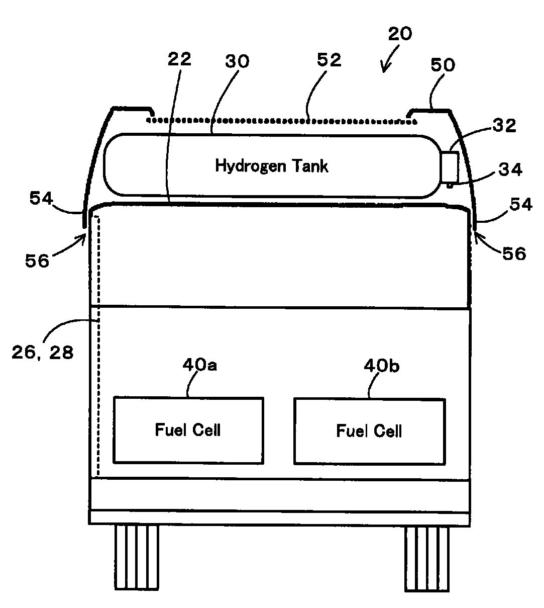
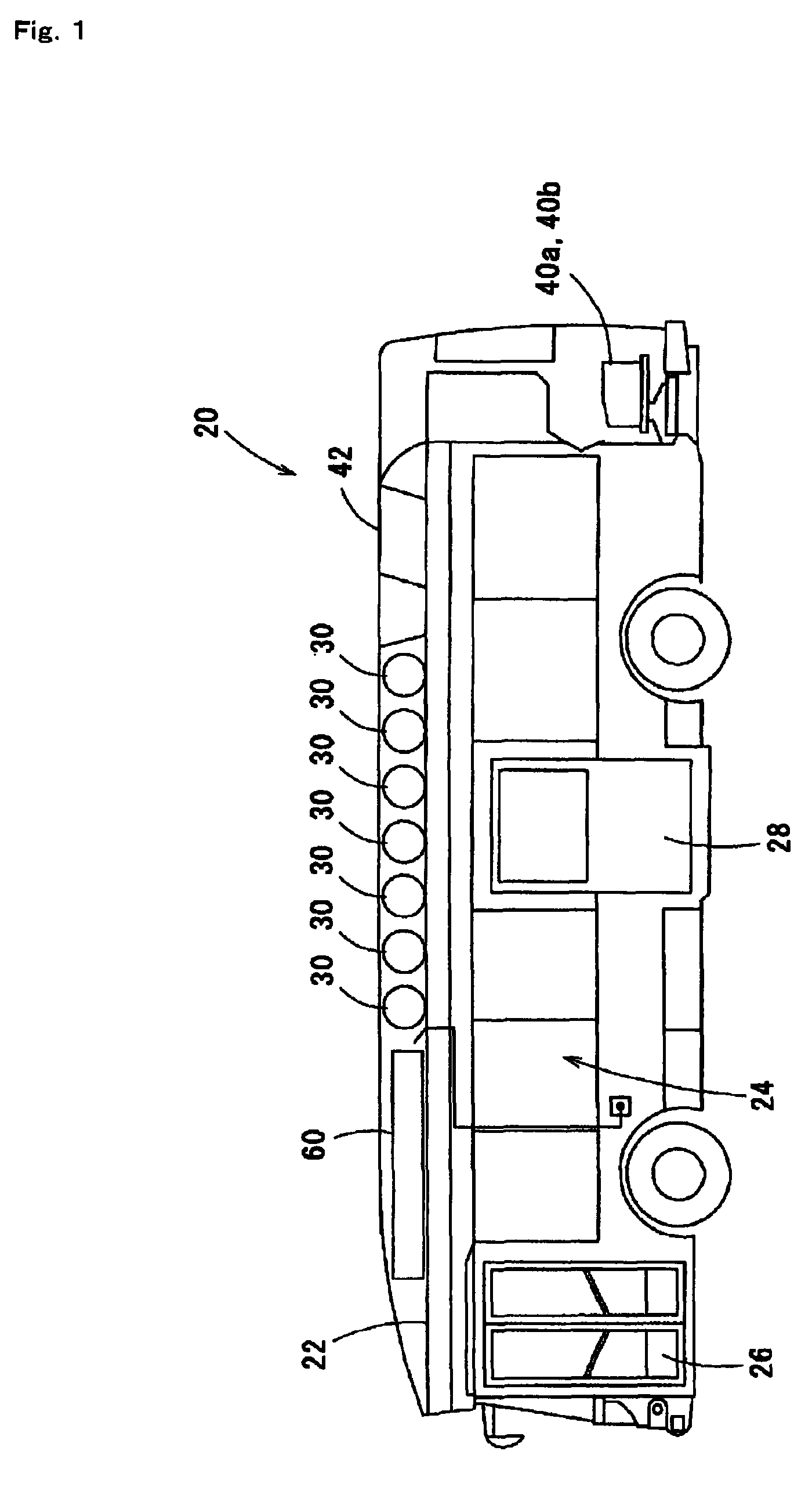
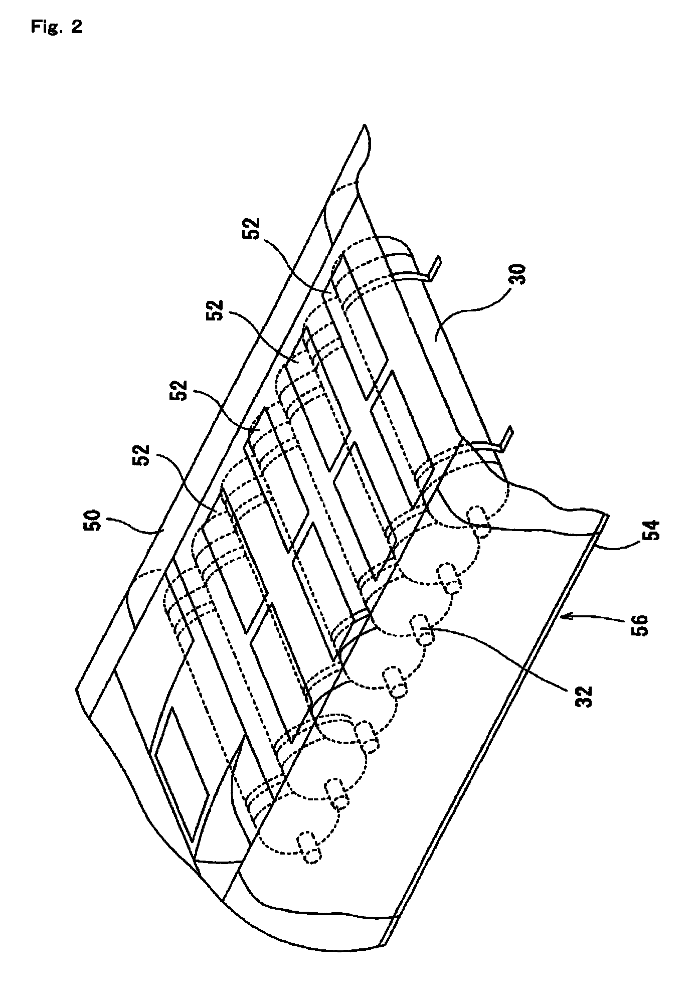
[0024]FIG. 1 is a schematic block diagram of a configuration of a fuel cell equipped bus 20 according to an embodiment of the present invention, FIG. 2 illustrates a state in which a hydrogen tank 30 is mounted on a roof 22 of the fuel cell equipped bus 20 of the embodiment. FIG. 3 illustrates a state in which fuel cells 40a and 40b and the hydrogen tank 30 are mounted in a rear portion and on the roof 22, respectively, of the fuel cell equipped bus 20, and FIG. 4 illustrates placement of the hydrogen tank 30 on the roof 22 of the fuel cell equipped bus 20. As shown, the fuel cell equipped bus 20 of the embodiment is configured as a large bus including a driver seat in a right front portion for passage on the left side, and a front platform 26 provided in a left side surface near the driver seat and a middle platform 28 provided in a left side surface in the middle, through whic...


PUM


Abstract

A hydrogen tank is mounted on a roof so that a valve unit mounted to one end in a longitudinal direction of the hydrogen tank is separated as far apart as possible from a front platform and a middle platform of a fuel cell equipped bus and so that the longitudinal direction of the hydrogen tank is in a lateral direction of a vehicle. Thus, even if hydrogen leaks from the valve unit or a fusible plug valve of the valve unit is fused to discharge hydrogen from the tank, the influence of the leaking or discharged hydrogen on the front platform and the middle platform can be reduced.

Description

[0001]This is a 371 national phase application of PCT / JP2006 / 300108 filed 6 Jan. 2006, which claims priority to Japanese Patent Application No. 2005-002273 filed 7 Jan. 2005, the contents of which are incorporated herein by reference.TECHNICAL FIELD[0002]The present invention relates to a vehicle and a method of mounting a gas fuel tank, and more particularly to a vehicle to which at least one gas fuel tank that stores gas fuel is mounted, and a method of mounting at least one gas fuel tank that stores gas fuel to a vehicle.BACKGROUND ART[0003]As a conventional vehicle of this type, a bus is proposed in which a plurality of gas fuel tanks each having a valve body mounted to a port opening at a front end in a longitudinal direction and store compression natural gas are mounted on a roof of a vehicle so that the longitudinal direction of the gas fuel tanks is in a vehicle fore / aft direction (for example, see Patent Document 1). In this vehicle, the longitudinal direction of the gas fu...

Claims


Application Information

Patent Timeline
Patent Type & Authority Patents(United States)
IPC IPC(8): B60K11/04B65D88/12B60P3/00B60K15/07B60H1/24B60H1/26B65D51/16B60H1/32B60K15/035B60K15/063B60K15/067
CPCB60K15/07B60Y2200/143B60K2015/0639B60Y2200/1432
Inventor MIZUNO, HIDEAKINAGANUMA, YOSHIAKI
Owner TOYOTA JIDOSHA KK
Why Eureka
Try Eureka