Latching mechanisms for clamshell type couplers

a technology of latching mechanism and clamshell, which is applied in the field of latching mechanism used in clamshell type couplers, can solve the problems of electrical spark hazard, instantaneous combustion, and electrical charge may rise, and achieve the effects of preventing electrostatic buildup, ensuring safety, and ensuring safety

Active Publication Date: 2016-02-16
EATON INTELLIGENT POWER LTD
View PDF52 Cites 14 Cited by
  • Summary
  • Abstract
  • Description
  • Claims
  • Application Information

AI Technical Summary

Benefits of technology

[0010]In addition to the latching assemblies, each of the embodiments may be supplemented with a secondary latch mechanism or latch indicator that is used to verify that the latch mechanism has properly been placed in a locked position. More specifically, the latch indicator serves as both a visual and tactile indicator for verification that the coupling is properly installed and secured over the interconnected fluid conveying members. The geometric arrangement of the latch indicator, as it is mounted on the coupling, is such that it can only be moved to its fully closed position when the latching mechanism is completely and properly locked. The latch indicator is easily visually inspected to confirm that it placed in its fully closed position during use. Further, a latching projection of the latch indicator provides an audible and tactile “snap” or “click” signifying that the latch mechanism has been placed in its fully locked position. The latch indicator also serves as a protective cover over the latch mechanism to prevent contact with the latch mechanism that could result in inadvertent unlocking of or damage to the latch mechanism.

Problems solved by technology

A stored electrostatic charge may give rise to an electrical spark hazard in the presence of vaporized fuel.
Discharge of the spark by grounding or by flexing of the coupling in such a manner to bring metallic parts of the coupling into contact with another may cause an instantaneous combustion of any vaporized fuel present at the time, which in turn can cause ignition of the fuel conveyed in the tubes.
Other causes of potential ignition include lightning strikes.

Method used


Image

  • Latching mechanisms for clamshell type couplers
  • Latching mechanisms for clamshell type couplers
  • Latching mechanisms for clamshell type couplers

Examples


first embodiment

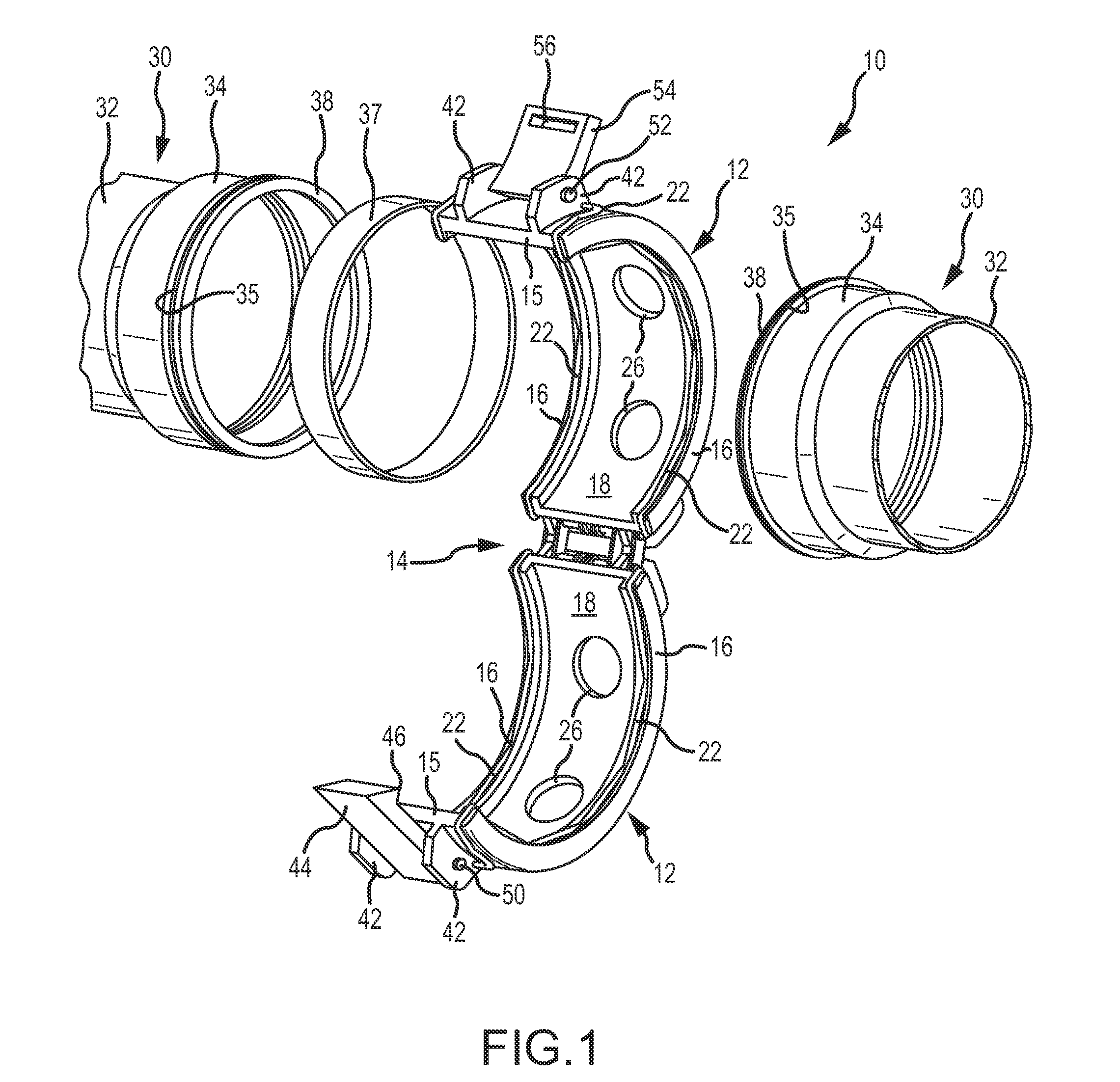
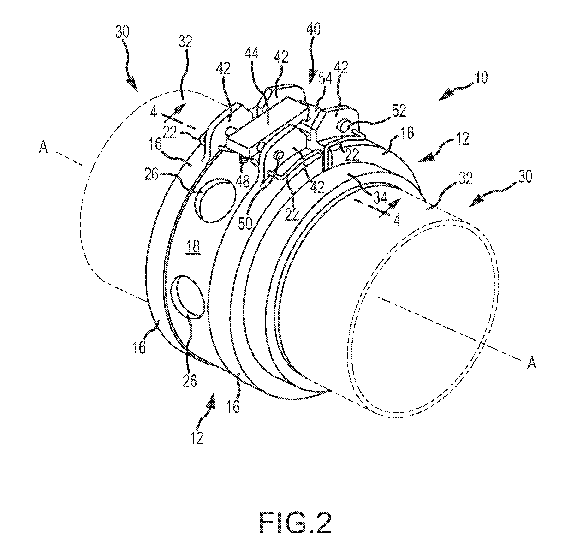
[0040]Referring to the drawings, and particularly to FIGS. 1-4, a threadless, clamshell type coupling assembly or coupler is illustrated in a first embodiment, and is generally indicated at 10. The coupling assembly comprises a pair of coupling halves 12 that are connected to one another along hinge 14. Each of the coupling halves 12 terminate along respective longitudinally extending faces 15. These faces define the free ends of the coupling halves that are placed in a confronting position to close the coupling and to thereby secure confronting ends of the fluid conveying members 30. A latching mechanism 40 is provided to positively and selectively lock the coupling halves to one another in a closed or coupled position. As shown, the coupling halves 12 are curved or arcuate in shape, and traverse an arc of approximately 180°.

[0041]The threadless clamshell type coupling assembly illustrated is especially adapted for use in fluid conveying applications, such as low pressure aircraft ...

second embodiment

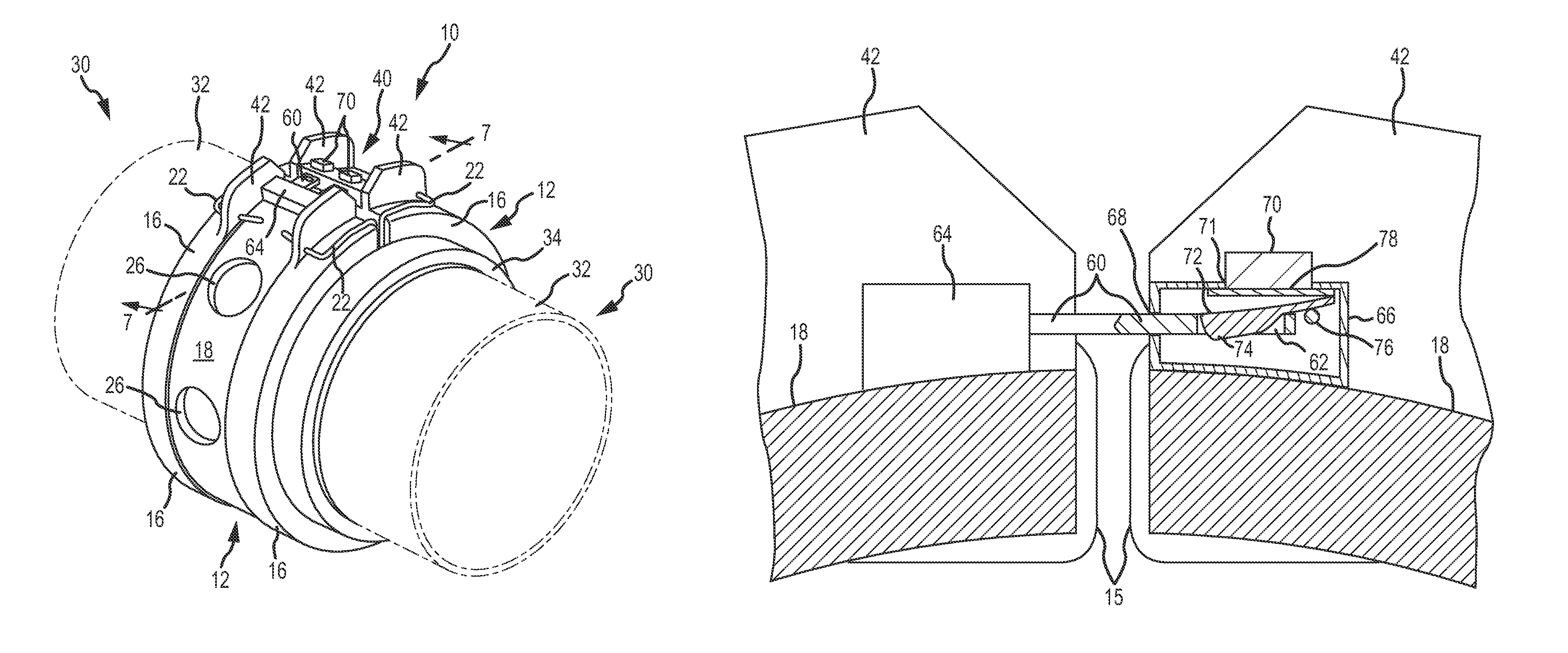
[0048]Referring to FIGS. 5-7, a latching mechanism 40 is illustrated in a A general principle of operation for this embodiment is the use one or more spring-loaded buttons that can be used to positively engage and lock the coupling assembly. Referring to FIGS. 6 and 7, the latching mechanism 40 includes a base or mount portion 64 mounted to a first coupling half and located between the respective latching mounts 42. Two extensions or tongues 60 extend circumferentially beyond the face 15 of the first coupling half towards the second coupling half. A latching hole 62 is formed in each of the extensions 60 as shown. The second coupling half includes a latching housing 66 with a pair of latching openings 68 sized and oriented for receiving the extensions 60. Each of the openings 68 communicate with a biased locking button 70 that may be manipulated by the user to lock and unlock the latching mechanism. Referring specifically to FIG. 7, one particular construction for the biased lockin...

fourth embodiment

[0051]Referring to FIGS. 11-13, a fourth embodiment is illustrated for the latch mechanism 40. This embodiment is characterized by a single latching arm 120 rotatably mounted on a pin 124 that traverses between adjacent latching mounts 42. The latching arm 120 includes a central rod or core 126, with a proximal end thereof having an opening to receive the mounting pin 124. A retention spring 128 is placed over the distal end of the central rod 126, and resides between the proximal end of the central rod 126 and a movable bushing 130 mounted over the central rod 126 distally of the spring 128. A spacer 132 is also placed over the distal end of the central rod 126, and resides distally of the movable bushing 130. A head or cap 122 attaches to the distal end of the rod 126. The movable bushing 130 may be selectively slid proximally along the central rod 126, thereby compressing the spring 128. The normal, biased position of the movable bushing 130 is shown in FIG. 12, in which the mova...


PUM


Abstract

Latching mechanisms in multiple embodiments connect clamshell type couplers comprising a pair of arcuate coupling halves joined at a hinge. One embodiment includes a biased catch lever that engages a corresponding latch plate. Another embodiment includes a plurality of latching extensions that engage an opposing latching housing, along with biased locking buttons for selectively locking the mechanism. Another embodiment includes dual rotatable latching arms for interconnecting the coupling halves, each arm having a latching cam for selectively locking the mechanism. Another embodiment includes a rotatable latching arm and a receiving bracket for receiving the latching arm for selectively locking the mechanism. Another embodiment includes an over center hinge mechanism including three cooperating and rotatable latch plates. Another embodiment includes cooperating cassette mechanisms, each having connector extensions for connecting the cassette mechanisms to one another for selectively locking the mechanism. Methods are also disclosed for selectively locking the latching mechanisms.

Description

FIELD OF THE INVENTION[0001]This invention relates to couplings for interconnecting a pair of confronting fluid conveying members, and more particularly, to latching mechanisms used in clamshell type couplers that interconnect fluid conveying members in a sealed relationship.BACKGROUND OF THE INVENTION[0002]Couplings used to interconnect fluid conveying tubes or conduits are found across many different industries, and special requirements may exist in each industry to address a number of standards. Many of the standards involve safety requirements to ensure the coupling creates a fluid tight seal across the facing ends of the tubes or conduits. For fluid conveying tubes that convey fuel, there is always a concern in the design of couplings to ensure that the design can provide means to dissipate electrostatic charges that will build up between insulated sections of the coupled tubes / conduits. A stored electrostatic charge may give rise to an electrical spark hazard in the presence o...

Claims


Application Information

Patent Timeline
Patent Type & Authority Patents(United States)
IPC IPC(8): F16L25/00F16L23/06F16L25/01F16L27/10
CPCF16L23/06F16L25/01F16L27/1012F16L27/1021F16L2201/10
Inventor SCHOOLEY, NICHOLAS CLANCYSTATLER, III, RICHARD LOWELLMARETICH, DAVID ETHANBREAY, CLIFTON PAULCAUDILL, JAY MACKTABER, JR., LANE CHARLESKOTTMEIER, THOMAS ALANADKINS, CHRIS T.RITTER, MICHAEL ALAN
Owner EATON INTELLIGENT POWER LTD
Why Eureka
Try Eureka