Dynamic load bearing shock absorbing exoskeletal knee brace

a knee brace and dynamic load technology, applied in the field of dynamic load bearing exoskeleton knee brace, can solve the problems of difficult control of damage resulting from meniscus tears, difficult control of meniscus damage, and failure of meniscus to maintain its integrity, etc., and achieve the effect of reducing the contact between the femur and the tibia

Active Publication Date: 2016-02-23
DESOUSA EGAS JOSE JOAQUIM
View PDF15 Cites 2 Cited by
  • Summary
  • Abstract
  • Description
  • Claims
  • Application Information

AI Technical Summary

Benefits of technology

[0009]A load bearing shock absorbing knee brace is provided. The knee brace is configured to be attached to the lower portion of the leg surrounding the tibia and an upper portion of the leg around the femur so as to reduce the load and the shock loads experienced by the knee joint as the individual uses the legs to walk or run.
[0010]In a first embodiment, the knee brace an upper sleeve assembly having a pair of upper struts fixed. One end of the upper struts are fixed to the sleeve. The sleeve is configured to engage the outer surface of the upper limb or thigh. The sleeve may have a conical shape similar to that of the human thigh to facilitate the desired load transfer from the sleeve to the thigh without the use of uncomfortably tight fits.
[0011]The other end of the struts are pivotally attached to a pair of shock absorbers. The shock absorbers may be tuned to specific energy absorption capabilities taking into account the effective impact weight of the individual using the knee brace, shock absorber stroke, internal return spring force and ease of integration. The shock absorbers are retained in a load bearing yet adjustable manner in a lower strut section that is to be strapped to the lower limbs. The other end of the lower strut may be removably attached to a shoe insert. The end of the lower strut may be inserted via a quick disconnect mechanism into a suitably designed hinged mechanism that is made part of a specially designed and built shoe.
[0013]Thus, when the individual stands up in the vertical position for instance, the movement of the leg forces the linkage 701-702-704 to decrease in length thereby forcing the shock absorber to close in until the new linkage length equals the length of the path in the leg 701-703-704. In this position the shock absorber is primed for action and the return springs push up against upper sleeve as far as the fastening conditions permit. As the individual walks or runs the movement of the limbs introduces sufficient movement to the shock absorbers to elicit a force response which helps in reducing the load on the knee. The shock absorber may be dimensioned to provide a force response directly proportional to the rate of change of position of its piston thus more vigorous and faster movements elicit a greater force response, and this helps reduce the load on the knee under shock and faster movement conditions.
[0014]The knee brace is configured to provide load bearing and shock absorbing function to the user's knee. It should be appreciated that the lower struts and the incorporation of the shoe insert to the shoe may be modified. In the first preferred embodiment the lower strut is pivotably connected to the back of the heel. This design allows the greatest degree of freedom for the foot. In a second preferred embodiment, the lower strut is pivotably mounted to a shoe sole insert having a pair of upwardly extending arms. For instance, the lower strut assembly may include a pair of lower struts, each fixedly connected to the pair of shock absorbers on one end, and pivotably connected to the pair of upwardly extending arms on the other end. In a third preferred embodiment, the knee brace may have a lower strut which includes a retaining sleeve configured to hold the pair of shock absorbers on one end of the lower strut, and a pair of retainers disposed on the end opposite the retaining sleeve, wherein the ends of the retainers are pivotably connected to a respective boot configured to engage a respective upwardly extending arm so as to position the lower strut in front of the calf when worn. In a fourth preferred embodiment, the knee brace includes a Y-shaped member configured to provide space for the knee to flex. In a fifth preferred embodiment, the knee brace includes a shock absorber support assembly configured to house the shock absorber coaxially with the lower strut.
[0018]By walking back and forth the individual can feel the shock absorber absorb part of the load on the knee. This results in immediate relief from the pain as the femur and tibia contact is reduced.

Problems solved by technology

The knee joint is the biggest joint in the human body and is subject to various failure modes.
One of the failure modes is the failure of the meniscus to maintain its integrity under sudden load spikes or accumulated damage.
The damage resulting from meniscus tears and other failure modes is hard to contain and control under normal everyday working load situations.
As the meniscus failure progresses the femur and the tibia come in direct contact resulting in irreversible damage under very painful conditions.
If untreated, the afflicted may find it unable to bear the pain, and may require the implantation of artificial knees.
Knee braces and supporting orthotics currently available are not configured to provide load bearing, and shock absorbing function.

Method used


Image

  • Dynamic load bearing shock absorbing exoskeletal knee brace
  • Dynamic load bearing shock absorbing exoskeletal knee brace
  • Dynamic load bearing shock absorbing exoskeletal knee brace

Examples


second embodiment

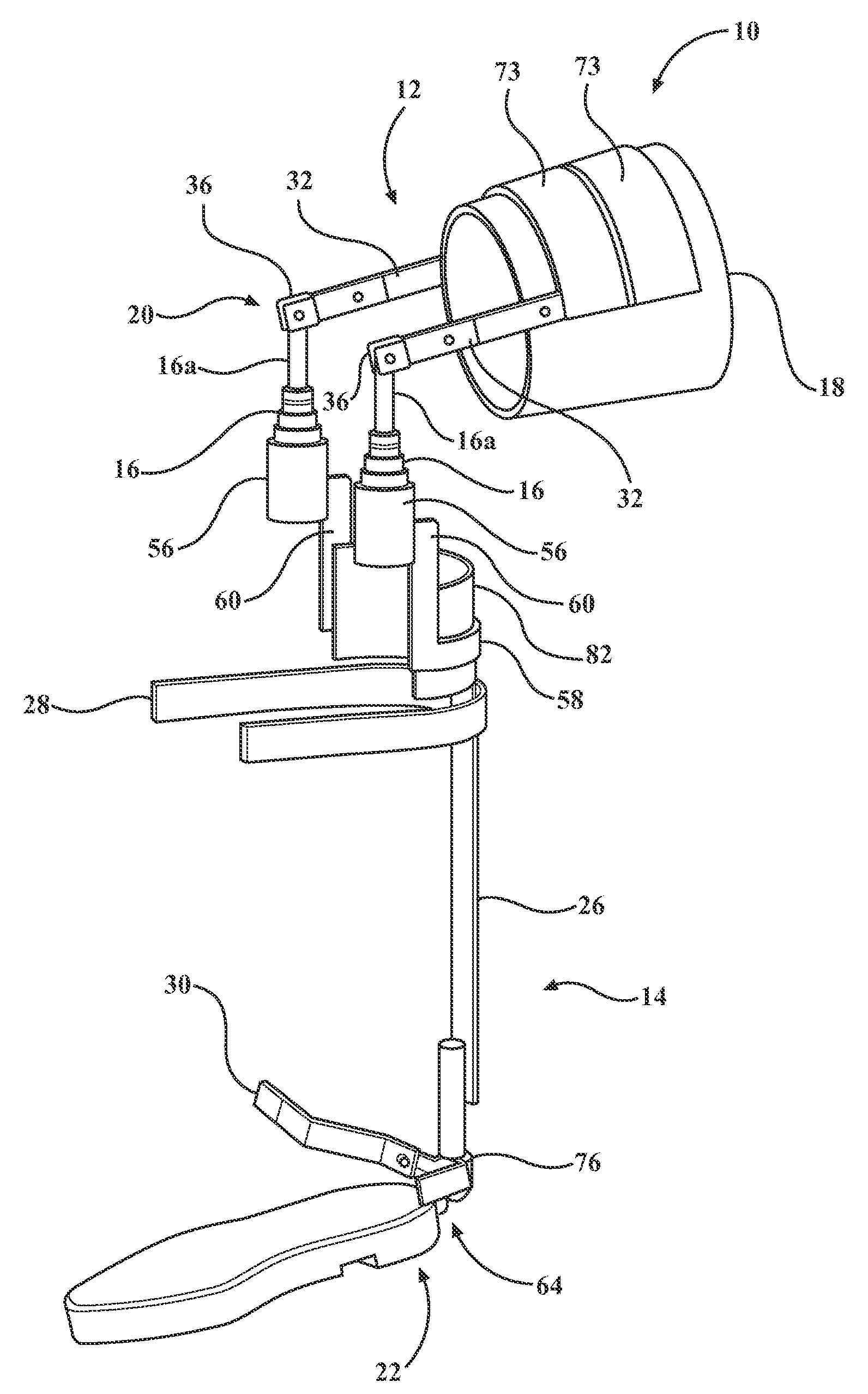
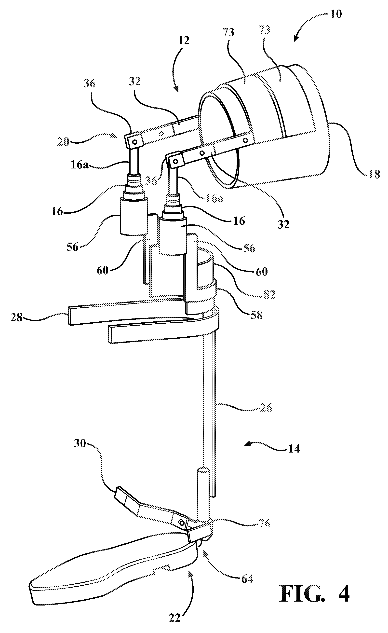
[0109]With reference now to FIG. 6 a second preferred embodiment of the brace 10, wherein like elements are referenced by like numbers increased by 100, adapted to be used with a shoe sole insert 122 having a pair of upwardly extending arms 84 is provided. The pair of upwardly extending arms 84 is rigidly fixed to the shoe sole insert 122. The shoe sole insert 122 made of a strong load bearing material as described above. Each of the pair of upwardly extending arms 84 is pivotably connected to the lower strut 126. The shoe sole insert 122 includes a base 88, dimensioned to support the foot of a user. In the second embodiment, the upper sleeve assembly 112 is pivotably connected to a pair of shock absorbers 116 in the same manner as described above.

[0110]With reference again to FIG. 6 and also to FIG. 11, the lower strut assembly 114 includes a pair of lower struts 126. The lower struts 126 have a top end 126a and a bottom end 126b. The lower struts 126 are generally axial and are sp...

fourth embodiment

[0116]With reference now to FIGS. 24-43, a fourth preferred embodiment of the knee brace 10, wherein like elements are referenced with like numbers increased by 300, is provided. The fourth embodiment utilizes the same principal of overcenter wherein the first pivot point 320 of the knee brace 310 is displaced above the natural pivot point of the user's knee. It is a further objective of the fourth preferred embodiment of the knee brace 310 to position the shock absorbers 316 so as to not interfere or rub against the leg of the user. It is another object of the fourth preferred embodiment of the knee brace 310 to position the upper struts 332 in alignment with the femur.

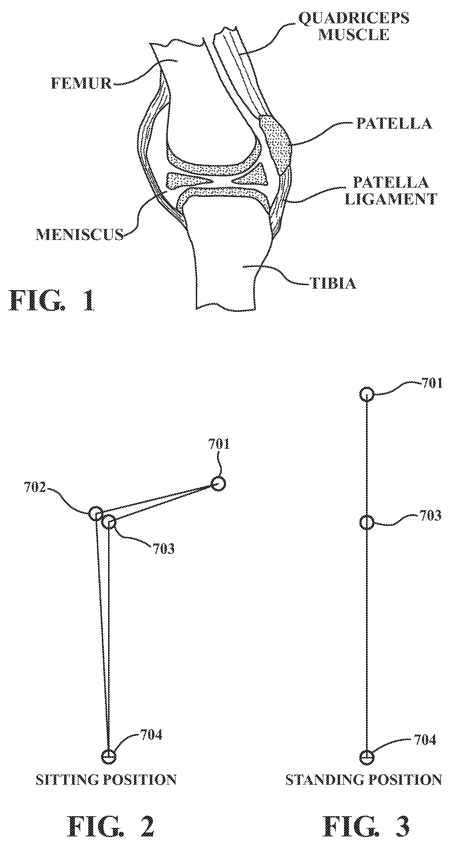
[0117]FIG. 22 and FIG. 23 show the methodology and design used to enable the overcenter principle to be used in a repeatable and reproducible manner, in the face of individual leg and knee size and shape variations. FIG. 23 shows the individual in the sitting position with 101 representing the thigh, 102 representing...


PUM


Abstract

The exoskeletal dynamic load bearing shock absorbing knee brace makes use of the energy absorbing characteristics of specifically designed industrial shock absorbers which are held precisely in place by an articulated dynamic exoskeletal structure that is to be secured to the lower limbs of the individual with the injured knee. The exoskeletal structure is designed using the principles of the overcenter linkage to translate and transfer to the shock absorbers a representative fraction of the normal and extra normal ambulatory movements of the lower limbs of the user which makes possible for these shock absorbers to absorb a corresponding amount of energy and provide an alternate load bearing structure parallel to the knees thus introducing a desirable degree of protection for the injured knee.

Description

CROSS-REFERENCE TO RELATED APPLICATIONS[0001]This is a continuation of U.S. Ser. No. 14 / 104,381, filed Dec. 12, 2013, which is a continuation-in-part of U.S. Ser. No. 13 / 902,835, filed May 26, 2013, which is a continuation-in-part of U.S. Ser. No. 13 / 555,165, filed Aug. 9, 2012.TECHNICAL FIELD[0002]A knee brace incorporating external shock absorbers configured to provide shock absorption of an articulated leg so as to reduce shock to the knee is provided.BACKGROUND OF THE INVENTION[0003]Injuries to the human knee joint resulting from participation in extreme sporting activities or resulting from accumulated damage with advancing years are all too common.[0004]The knee joint is the biggest joint in the human body and is subject to various failure modes. One of the failure modes is the failure of the meniscus to maintain its integrity under sudden load spikes or accumulated damage. The meniscus is an avascular cartilage that acts as a shock absorber inside the knee. There are two disc...

Claims


Application Information

Patent Timeline
Patent Type & Authority Patents(United States)
IPC IPC(8): A61F5/00A61F5/01
CPCA61F5/0125A61F5/0102A61F5/0123A61F2005/0169
Inventor DESOUSA, EGAS, JOSE-JOAQUIM
Owner DESOUSA EGAS JOSE JOAQUIM
Why Eureka
Try Eureka