Supercharge Your Innovation With Domain-Expert AI Agents!

Light emitting diodes for simulation of missile signatures

a light-emitting diode and missile technology, applied in the field of missile simulation, can solve the problem that the background radiation of the sun can introduce significant nois

Active Publication Date: 2016-02-23
SENSOR ELECTRONICS TECH
View PDF13 Cites 4 Cited by
  • Summary
  • Abstract
  • Description
  • Claims
  • Application Information

AI Technical Summary

Benefits of technology

The system effectively simulates the missile plume's irradiance signature, enhancing the accuracy of missile detection and tracking by replicating the plume's radiation patterns and accounting for atmospheric conditions, thereby improving the precision of missile warning systems.

Problems solved by technology

However, unoxidized fuel materials typically mix with ambient air downstream of the plume core and produce a higher temperature afterburning mixing region with temperatures as high as 3000 Kelvin.
Additionally, sun background radiation can introduce significant noise, which for certain light wavelengths, can be comparable in amplitude with the plume's light signal.

Method used


Image

  • Light emitting diodes for simulation of missile signatures
  • Light emitting diodes for simulation of missile signatures
  • Light emitting diodes for simulation of missile signatures

Examples


Embodiment Construction

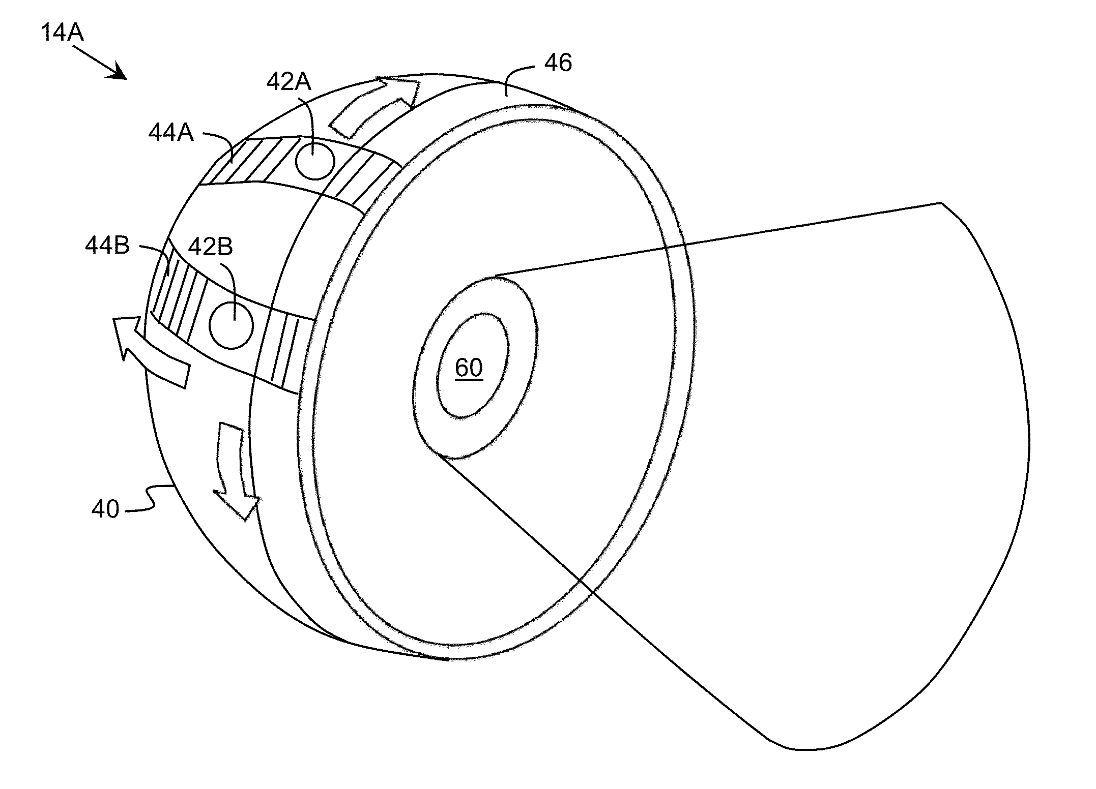
[0024]In general, aspects of the invention are directed to simulating an irradiance signature of a missile plume. The simulation can be performed using one or more emitting structures, each of which can be configured to emit radiation corresponding to any of a plurality of possible plume irradiance signatures corresponding to a missile. The radiation emitted by an emitting structure can include ultraviolet, infrared, and / or visible radiation. Various aspects of the emitted radiation can be adjusted to account for different possible plumes being simulated for the missile. The emitting structures can be utilized, for example, as part of an evaluation of a missile warning system.

[0025]As indicated above, aspects of the invention provide an emitting structure for simulating an irradiance signature of a missile. The emitting structure includes one or more radiation sources, each of which includes at least one ultraviolet radiation source and at least one infrared radiation source. The em...


PUM


Abstract

An emitting structure for simulating an irradiance signature of a missile is provided. The emitting structure includes one or more radiation sources, each of which includes at least one ultraviolet radiation source and at least one infrared radiation source. The emitting structure also includes a spherical shell and a mechanism for positioning the radiation source(s) along a three dimensional boundary of the spherical shell. The emitting structure can locate and operate one of the radiation sources to simulate the irradiance signature of the missile.

Description

REFERENCE TO RELATED APPLICATIONS[0001]The current application claims the benefit of co-pending U.S. Provisional Application No. 61 / 538,125, titled “Light Emitting Diodes for Simulation of Missle Signatures,” which was filed on 22 Sep. 2011, and which is hereby incorporated by reference.TECHNICAL FIELD[0002]The disclosure relates generally to missile simulation, and more particularly, to simulating an irradiance signature of a missile plume using light emitting diodes.BACKGROUND ART[0003]A rocket exhaust plume consists of heated gas moving at a high speed and at a high temperature. This gas formation is inhomogeneous in structure, has a non-uniform velocity, and a non-uniform composition. Frequently, a plume contains supersonic shock waves with high gradients of pressure and temperature across the wave region. The plume characteristics, e.g., its size and shape, light emission intensity, and spectral signature, depend not only on the rocket aerodynamic characteristics and the rocket...

Claims


Application Information

Patent Timeline
Patent Type & Authority Patents(United States)
IPC IPC(8): G06F17/50G06G7/56G06G7/48F41J2/00F41J9/08F41H11/02
CPCF41J2/00F41J9/08F41H11/02F41G7/002F41J2/02F41J9/00
Inventor GASKA, REMIGIJUSDOBRINSKY, ALEXANDERSHATALOV, MAXIMSHUR, MICHAEL
Owner SENSOR ELECTRONICS TECH
Features
  • R&D
  • Intellectual Property
  • Life Sciences
  • Materials
  • Tech Scout
  • Unparalleled Data Quality
  • Higher Quality Content
  • 60% Fewer Hallucinations
Learn More