

Vaporizer with combined air and radiation heating
a technology of combined air and radiation heating, which is applied in the direction of medical atomizers, inhalators, medical devices, etc., can solve the problems of limited operation, limited disadvantages, and insufficient vaporization
- Summary
- Abstract
- Description
- Claims
- Application Information
AI Technical Summary
Benefits of technology
Problems solved by technology
Method used
Image

Examples
Embodiment Construction
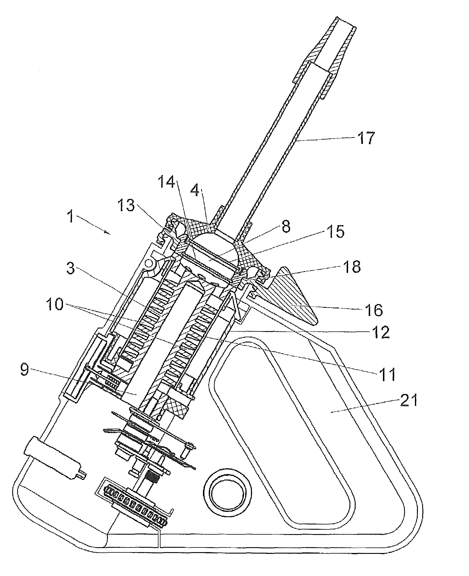
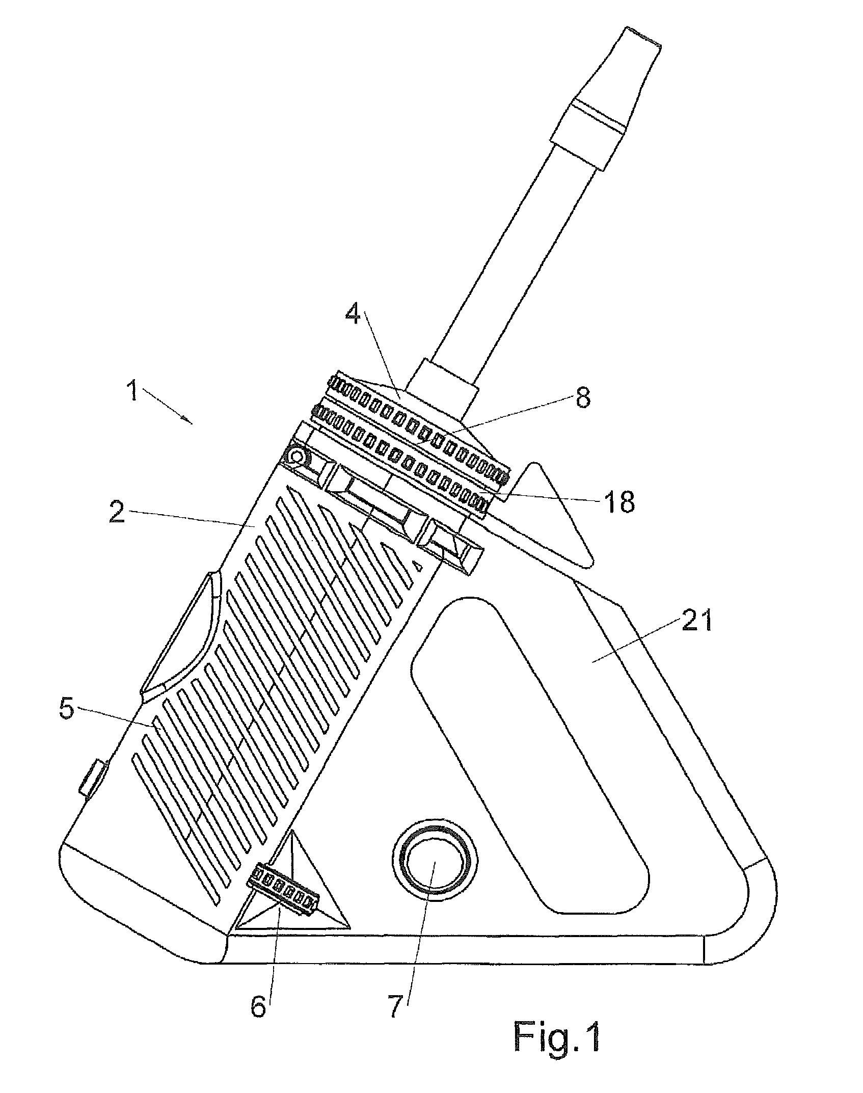
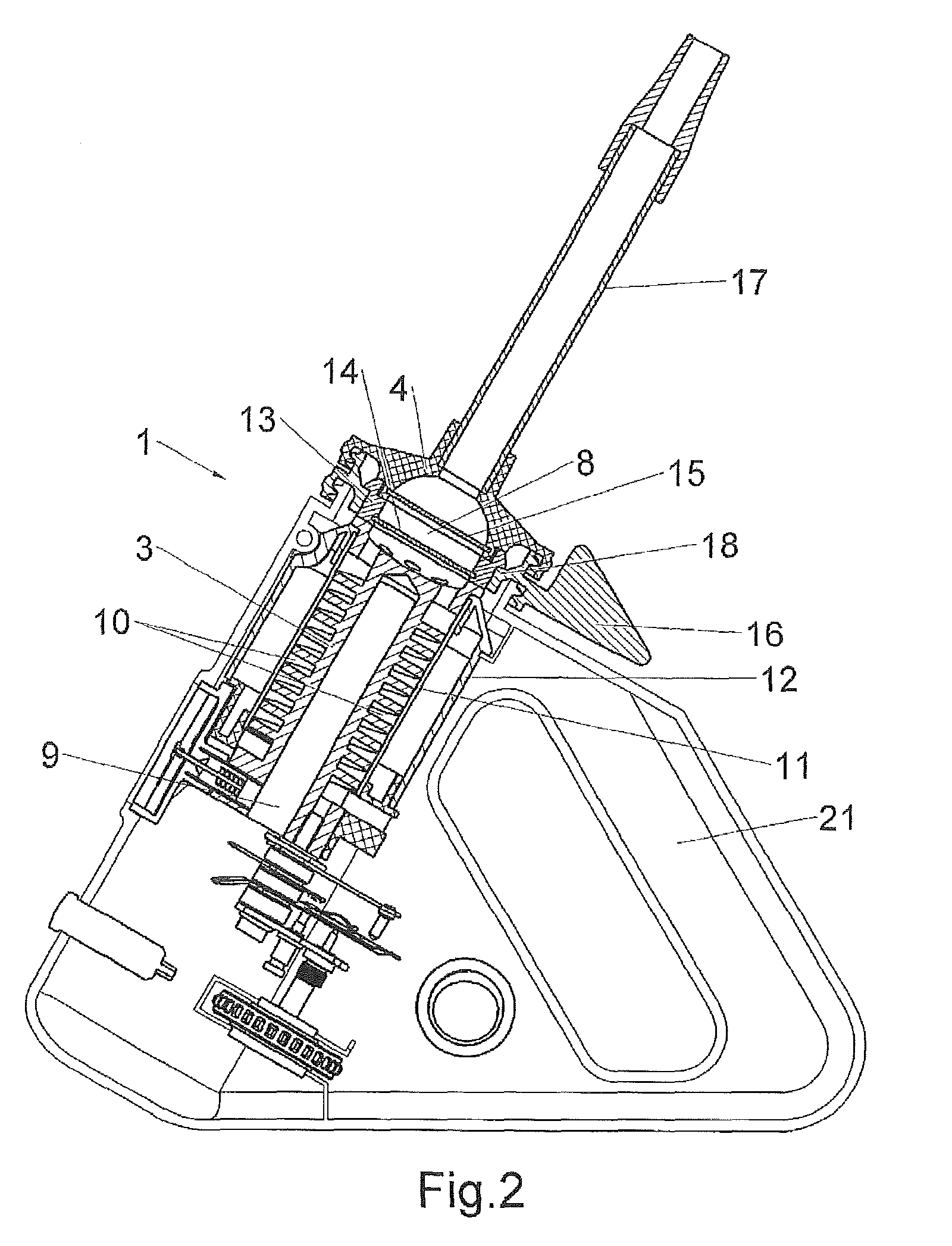
[0013]It is the idea of the invention that heating in a hot air extraction vaporizer can be enhanced such that an immediate vaporization takes place that also continues throughout the inhalation process.
[0014]Accordingly, the hot air extraction vaporizer according to the invention comprises a heater that is capable of heating the filling chamber as well as capable of generating a hot airflow that is guided through the content of the filling chamber. For this purpose, the heater, which may be designed as a solid heat exchanger and comprise one or more air channels running through the heat exchanger, may preferably according to one embodiment comprise a filling chamber that is integrated into the heat exchanger; and according to another preferred embodiment a detachable filling chamber, that is in the attached state thermally coupled via a contact face with the heat exchanger. The inner wall of the filling chamber is in both cases designed to heat up the content of the filling chamber...
PUM
 Abstract
Description
Claims
Application Information