Method of making a porous sintered body, a compound for making the porous sintered body, and the porous sintered body

a technology of porous sintered body and compound, which is applied in the field of methods of making porous sintered body, compound for forming porous sintered body, and porous sintered body, can solve the problems of pore formation material changing shape, and achieve the effect of maintaining a level of strength required, sufficient strength, and high strength

Active Publication Date: 2016-03-01
TAISEI KOGYO CO LTD
View PDF9 Cites 1 Cited by
  • Summary
  • Abstract
  • Description
  • Claims
  • Application Information

AI Technical Summary

Benefits of technology

[0014]According to the present invention, first, a pellet making step is performed for forming pellets applicable to thermal formation process such as injection molding, thermal protrusion, etc. In the pellet making step, mixing is performed at temperatures which allow the binder to melt but do not allow the pore formation material to soften, so as to ensure ease of formation in the step thereafter. When heated, the pellets gain increased fluidity, enabling the thermal forming step to be performed in such conventional ways as injection molding. The thermal formation step is performed also at temperatures which allows the binder to melt but do not allow the pore formation material to change its shape. In the degreasing step according to the present invention, the pore formation material is drained while part of the binder remains. Since the pore formation material is to drain first, the binder contains components which melt at temperatures in the pellet making step and the formation step, and drains at temperatures higher than a draining temperature of the pore formation material. It should be noted here that the binder in the present invention includes any components other than the sintering compound and the pore formation material, contained in the formed body after the formation and capable of providing shape retentionability during the degreasing step. When the pore formation material drains, the remaining binder binds the sintering compound around the pore formation material, thereby enhancing shape retentionability. On the other hand, not all amount of the binder component is kept until the pore formation material has drained, but an amount of the binder necessary for providing gaps for the pore formation material to drain is drained before the pore formation material. This eliminates collapsing of sintering compound particles around the pore formation material during the degreasing step, making possible to form pores of highly precise shape and dimensions. Further, letting part of the binder remain un-drained increases strength of the formed body after the pore formation, making possible to perform intermediate processing such as filling the pores with functional particles described earlier.
[0051]Porous formed bodies which have a higher porosity become lower in shape retention strength after the pore formation material drains. Therefore, quick draining of the remaining binder increases a risk of deformation for example. The present invention enables to drain remaining binder without posing excessive stress after the pore formation material has been drained.

Problems solved by technology

The thermal formation step is performed also at temperatures which allows the binder to melt but do not allow the pore formation material to change its shape.

Method used


Image

  • Method of making a porous sintered body, a compound for making the porous sintered body, and the porous sintered body
  • Method of making a porous sintered body, a compound for making the porous sintered body, and the porous sintered body
  • Method of making a porous sintered body, a compound for making the porous sintered body, and the porous sintered body

Examples


Embodiment Construction

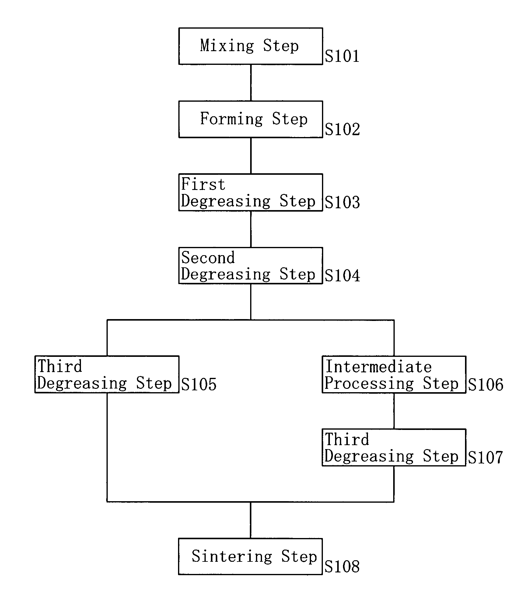
[0063]Hereinafter, description will cover embodiments which are application examples of the methods of making porous sintered bodies according to the present invention to metal powder injection molding.

[0064]

TABLE 1MixingBinderDrainRatioComponentStartingDrainParticleto AllRatioTemp.Temp.CompositionComponentSize(Vol %)(Vol %)(° C.)(° C.)Pore FormationPMMA50 μm60100240400MaterialMetal PowderSUS316L10 μm20Binder AWax12.864100210340(Low-temp.)Binder BPOM2.110.5352488(High-temp.)PP5.125.5255497

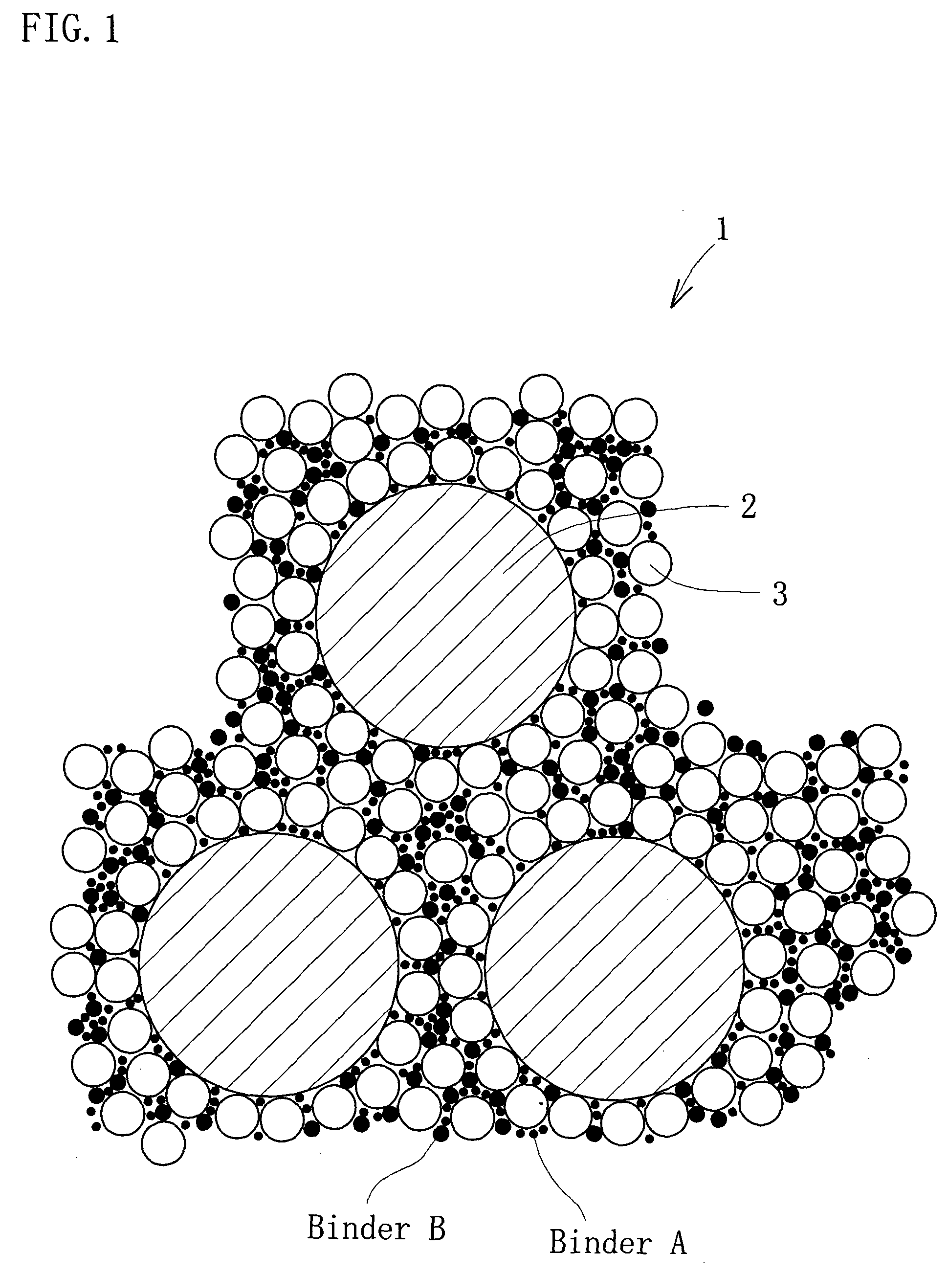
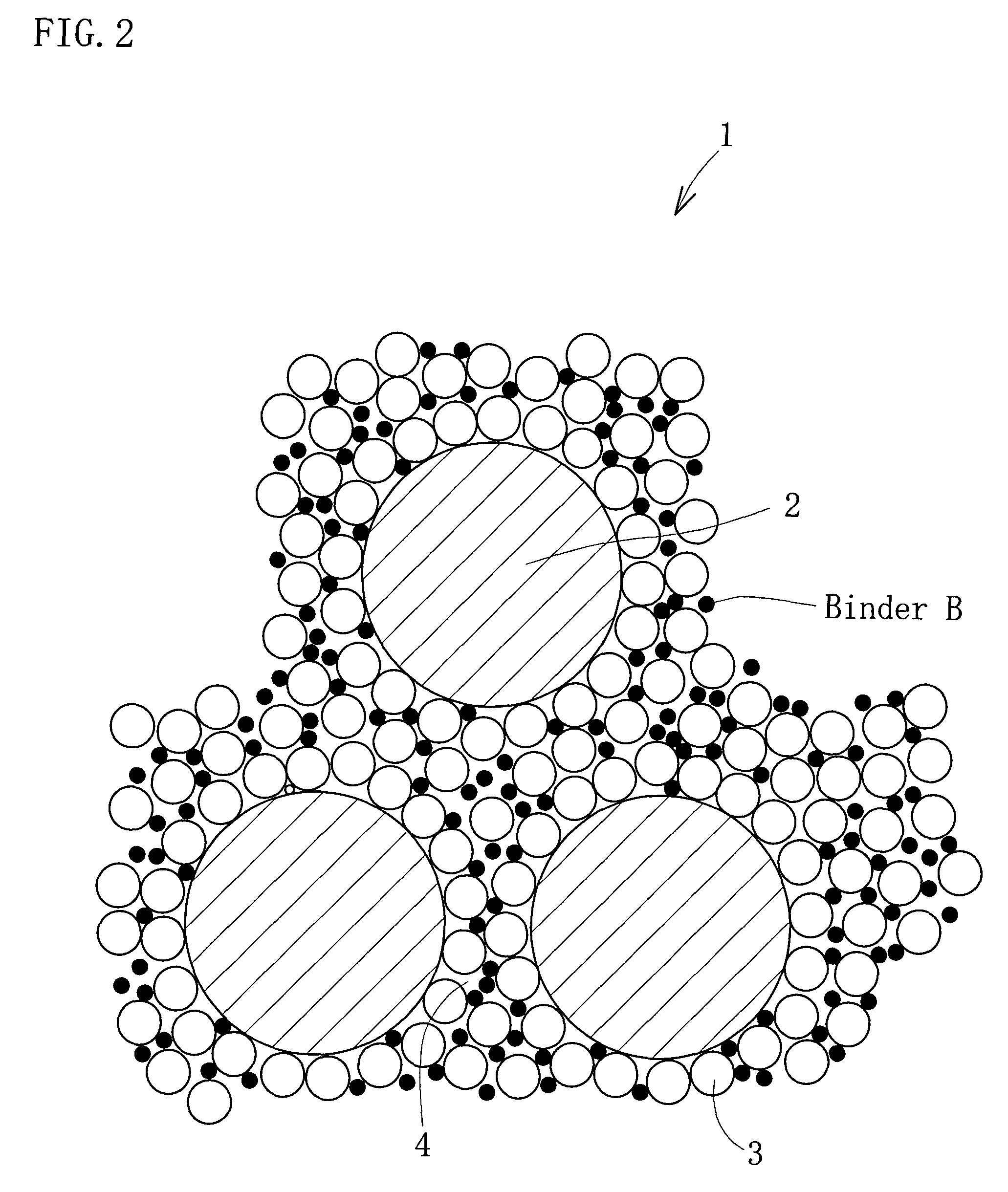
[0065]In the present embodiment example, materials and conditions as shown in Table 1 are used: Metal powder is provided by SUS 316L which has an average particle size of 10 μm; pore formation material is provided by PMMA (polymethylmethacrylate resin) which has an average particle size of 50 μm. In addition, binders are provided by three kinds of binder components; i.e. wax (a compound wax made of natural wax and synthetic was), POM (polyacetal) and PP (polypropylene). These components are mixed u...


PUM

PropertyMeasurementUnit
porosityaaaaaaaaaa
porosityaaaaaaaaaa
volume percentaaaaaaaaaa

Abstract

A method of making a porous sintered body includes a formation step S102 where a sintering compound which contains a binder and a sinterable powder material is into a predetermined shape; a degreasing steps S103, S104 and S105 where the binder is removed from a formed body obtained in the formation step; and a sintering step S108 where a degreased body after the degreasing step is sintered into a sintered body. The binder contains a component which drains at a temperature higher than a draining temperature of the pore formation material drains. The pore formation material is drained in the degreasing step, with part of the binder remaining un-drained. The present invention enables to manufacture porous sintered bodies which are highly porous, and highly accurate in shape and dimensions. The present invention also enables to manufacture porous sintered bodies which offer functionalities not available before.

Description

TECHNICAL FIELD[0001]The present invention relates to methods of making porous sintered bodies, compounds for forming porous sintered bodies, and porous sintered bodies. Specifically, the present invention relates to methods and related techniques for accurately forming porous sintered bodies which have a high rate of porosity.BACKGROUND ART[0002]Numerous products are manufactured from a porous sintered body i.e. a material that has a multiple of voids within. These products include filters, catalysts for chemical reactions, electrodes, heat exchangers and so on. When the pores are used to hold lubricant oil or the like, the porous sintered body can be used as a material for bearings.[0003]Methods of manufacturing the porous sintered body include casting method, foaming method, plating method, etc. Another method is space holder method: In this method, powdery sintering compound is mixed with a pore formation material which is a compound that is removed by heat. The mixed compound i...

Claims


Application Information

Patent Timeline
Patent Type & Authority Patents(United States)
IPC IPC(8): B22F3/11C04B38/02B22F7/00B22F3/10C04B38/04C04B111/00
CPCB22F3/1121B22F3/1021C04B38/02C04B38/04C04B35/00C04B40/0268B22F2998/10C04B2111/0081C04B2111/00793C04B2111/00844Y10T428/268B22F1/0059B22F3/225B22F3/10C04B38/06
Inventor TANAKA, SHIGEOISHIDA, SHINJINISHIYABU, KAZUAKI
Owner TAISEI KOGYO CO LTD
Why Eureka
Try Eureka