
Light modulator and illumination system of a microlithographic projection exposure apparatus

a technology of exposure apparatus and light modulator, which is applied in the direction of microlithography exposure apparatus, printers, instruments, etc., can solve the problems of adding to the complexity and cost of the illumination system, and achieve the effect of reducing the risk of significant heat generation of light and/or damaging the sensitive components that are arranged underneath the mirror

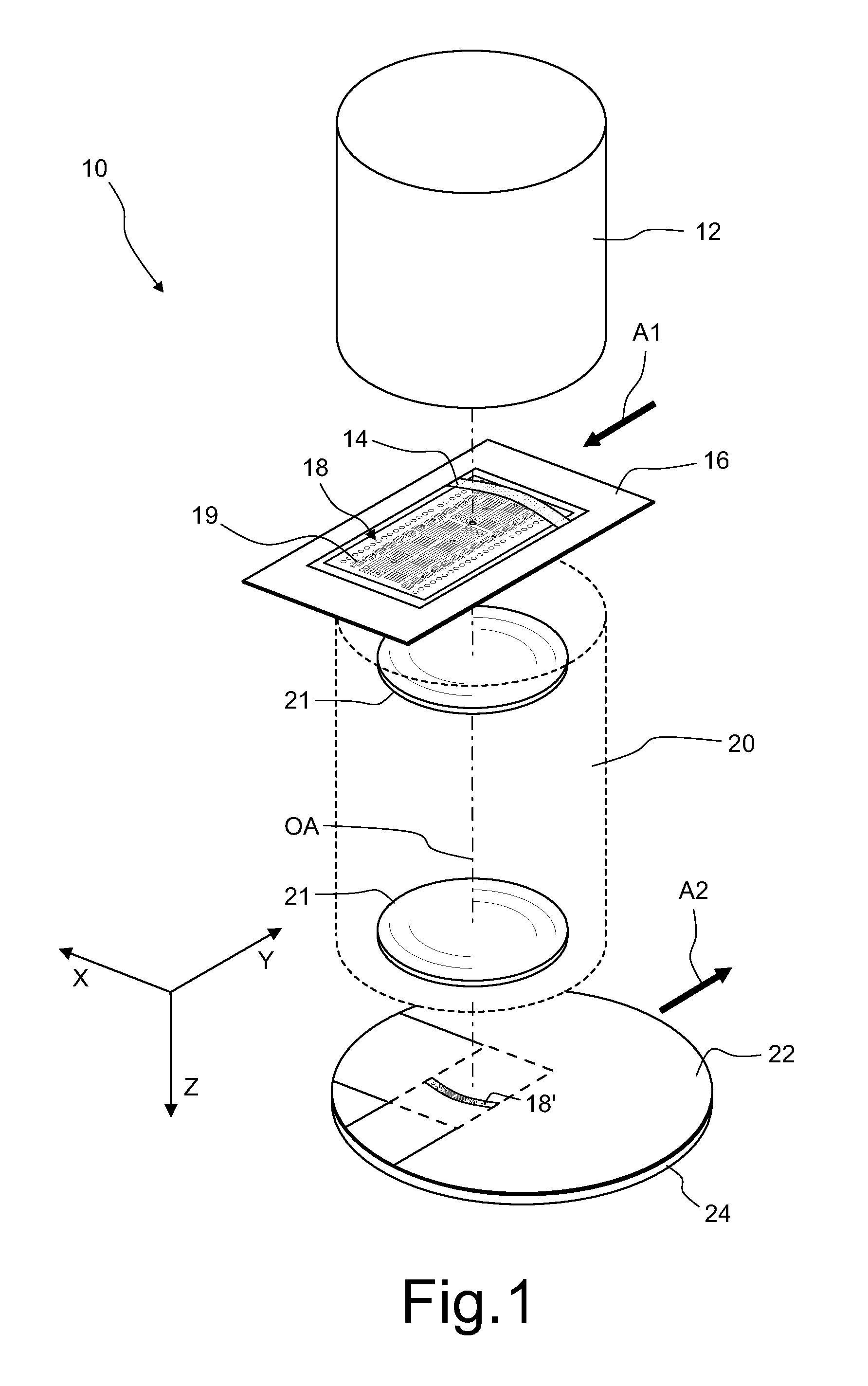
Active Publication Date: 2016-03-01
CARL ZEISS SMT GMBH
View PDF21 Cites 0 Cited by
  • Summary
  • Abstract
  • Description
  • Claims
  • Application Information

AI Technical Summary

Benefits of technology

[0017]It is an object of the present invention to provide a light modulator in which the risk that light significantly heats up and / or damages sensitive components that are arranged underneath the mirrors of the mirror array is reduced.
[0018]It is a further object of the present invention to provide an illumination system of a microlithographic projection exposure apparatus comprising an array of mirrors. The illumination system shall not require concentrating optics that separates the projection light into a plurality of sub-beams, but there shall be no risk that projection light significantly heats up and / or damages sensitive components that are arranged underneath the mirrors of the mirror array.
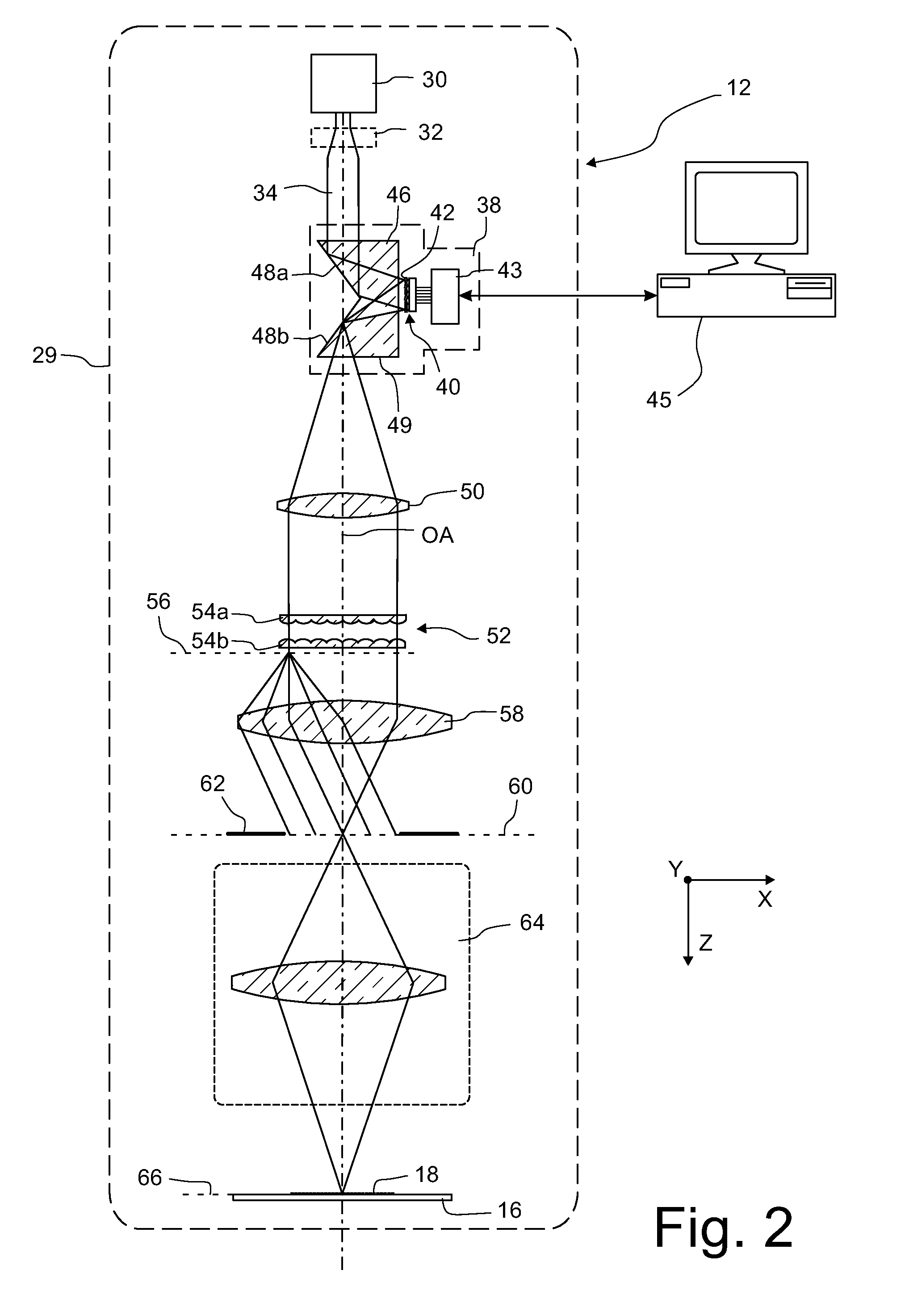
[0021]The invention is most advantageous if the light modulator comprises illumination optics that is arranged between a light source and the array of mirrors and directs the light on the array of mirrors such that the latter is illuminated by at least one light beam which extends over at least some adjacent mirrors. However, the invention may also be used in optical systems in which concentrating optics produce a plurality of individual sub-beams that are separated from each other. Then the overlapping arrangement of the mirrors prevents stray light from reaching sensitive components that are arranged on the modulator substrate of the mirror array.
[0030]It is a further objective to provide a light modulator that produces less stray light during its operation.
[0032]This avoids a perfectly regular arrangement and thus helps to prevent diffraction induced stray light.

Problems solved by technology

However, such a concentrating optics adds to the complexity and costs of the illumination system.

Method used


Image

  • Light modulator and illumination system of a microlithographic projection exposure apparatus
  • Light modulator and illumination system of a microlithographic projection exposure apparatus
  • Light modulator and illumination system of a microlithographic projection exposure apparatus

Examples


first embodiment

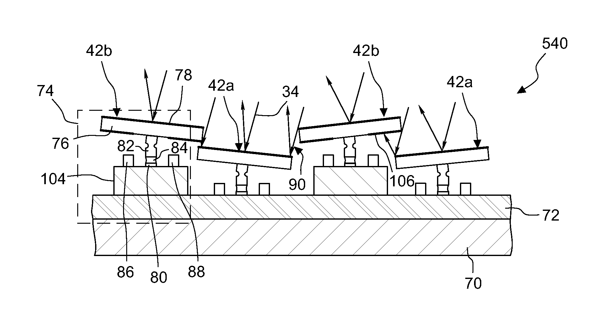
[0068]FIG. 5 is a sectional view through a portion of the mirror array 40 according to a The mirror array 40 comprises a substrate 70 which supports a plurality of electronic components 72 which are not shown in detail, but only as a single circuit layer. The substrate 70 further supports a plurality of mirror units 74 each comprising one of the micromirrors 42 and those electronic components that are functionally associated with the micromirror 42. Each micromirror 42 comprises, in turn, a mirror substrate 76 and a reflective coating 78 applied thereon and consisting, for example, of a plurality of thin layers having alternate refractive indices.

[0069]Each mirror unit 74 further comprises a base 80 which supports two solid state joint members 82, 84 which enable the micromirrors 42 to tilt around two orthogonal tilt axes that are defined by the configuration of the solid state joint members 82, 84. Also included in each mirror unit 74 is a plurality of actuators 86, 88 that are co...

second embodiment

[0074]FIG. 6 is a sectional view through a portion of a mirror array 240 according to a In this embodiment the absorber elements 94 are not attached to the substrate 70, the actuators 86, 88 or the electronic components that are supported by the substrate 70, but are attached to edges 98 of the micromirror substrates 76. The absorber elements 94 have an angled cross-section which is determined such that the micromirrors 42 are still allowed to freely tilt, together with the absorber elements 94, around the two tilt axes without getting in contact with an adjacent micromirror. Attaching the absorber elements 94 to the micromirror substrates 76 has the advantage that no projection light at all is allowed to penetrate into the gaps 90. Therefore heat, which is produced by absorption of the projection light in the absorber elements, is kept away from the sensible electronic components 72 and the actuators 86, 88 and can be more easily removed from the mirror array 240 by a gas flowing ...

third embodiment

[0076]In the third embodiment shown in FIG. 7 the mirror array 340 comprises absorber elements 94 that are arranged on ridges 100 that stand erect from the substrate 70 between the micromirrors 42. The effect is similar to the absorber elements 94 of the mirror array 240 shown in FIG. 6.


PUM

PropertyMeasurementUnit
wavelengthsaaaaaaaaaa

Abstract

An illumination system of a microlithographic projection exposure apparatus comprises a light modulator which includes a modulator substrate and an array of mirrors that are supported by the modulator substrate. At least some adjacent mirrors partly overlap. The light modulator further comprises a plurality of actuators that are supported by the modulator substrate and are configured to tilt the mirrors individually.

Description

CROSS-REFERENCE TO RELATED APPLICATIONS[0001]The present application is a continuation of, and claims benefit under 35 USC 120 to, international application PCT / EP2011 / 005737, filed Nov. 15, 2011. The entire disclosure of international application PCT / EP2011 / 005737 is incorporated by reference herein.BACKGROUND OF THE INVENTION[0002]1. Field of the Invention[0003]The invention generally relates to a light modulator comprising an array of mirrors and more specifically to an illumination system of a microlithographic projection exposure apparatus comprising such a light modulator.[0004]2. Description of Related Art[0005]Microlithography (also referred to as photolithography or simply lithography) is a technology for the fabrication of integrated circuits, liquid crystal displays and other microstructured devices. The process of microlithography, in conjunction with the process of etching, is used to pattern features in thin film stacks that have been formed on a substrate, for example...

Claims


Application Information

Patent Timeline
Patent Type & Authority Patents(United States)
IPC IPC(8): G03B27/54G03B27/72G03F7/20G02B26/08
CPCG03F7/70191G02B26/0833G02B26/0841G03F7/70058G03F7/70116
Inventor WERBER, ARMINWALDIS, SEVERINBACH, FLORIAN
Owner CARL ZEISS SMT GMBH
Learn More