
Printing head module

a printing head and module technology, applied in printing and other directions, can solve problems such as contamination of printing objects, and achieve the effects of enhancing the printing quality of 3-d printing objects, preventing contamination of the base surface, and simplifying the cleaning and maintenance process of nozzle tips

Active Publication Date: 2016-03-08
XYZPRINTING +2
View PDF2 Cites 3 Cited by
  • Summary
  • Abstract
  • Description
  • Claims
  • Application Information

AI Technical Summary

Benefits of technology

The patent describes a printing head module with a wiper unit that cleans the nozzle tips of printing heads that are not currently in use. This prevents residual modeling material from dropping from the nozzle and contaminating the surface being printed, resulting in improved printing quality. It also simplifies the process of cleaning and maintenance.

Problems solved by technology

However, as the printing head is switched from one to another, often there is still residual modeling material left on the nozzle tips of the printing head which just finishes the printing task.
Accordingly, the residual modeling material left on the nozzle tips of those printing heads might drop on the printing surface, which cause the contamination issues on the printing objects.

Method used


Image

  • Printing head module
  • Printing head module
  • Printing head module

Examples


Embodiment Construction

[0015]It is to be understood that both of the foregoing and other detailed descriptions, features, and advantages are intended to be described more comprehensively by providing embodiments accompanied with figures hereinafter. In the following embodiments, wordings used to indicate directions, such as “up,”“down,”“front,”“back,”“left,” and “right”, merely refer to directions in the accompanying drawings. Therefore, the directional wording is used to illustrate rather than limit the exemplary embodiments. The present embodiment is approximately identical to the second embodiment, and same or similar reference numerals used in the present embodiment and in the second embodiment represent the same or similar elements.

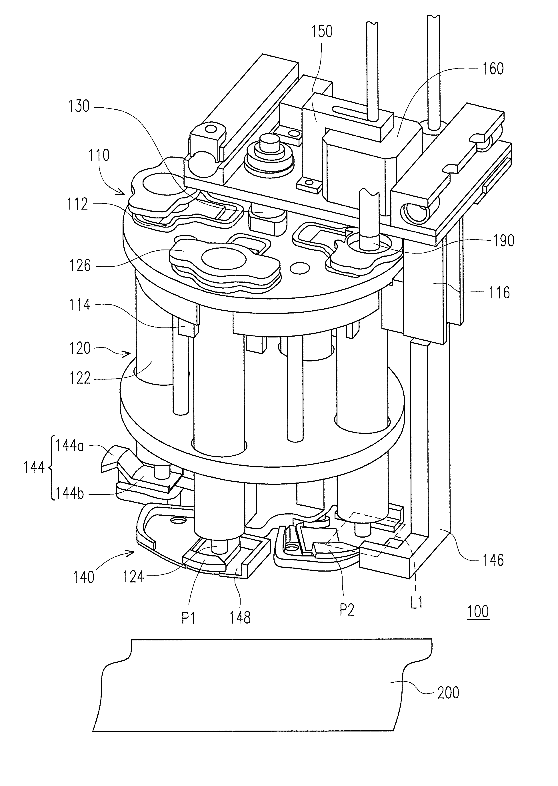
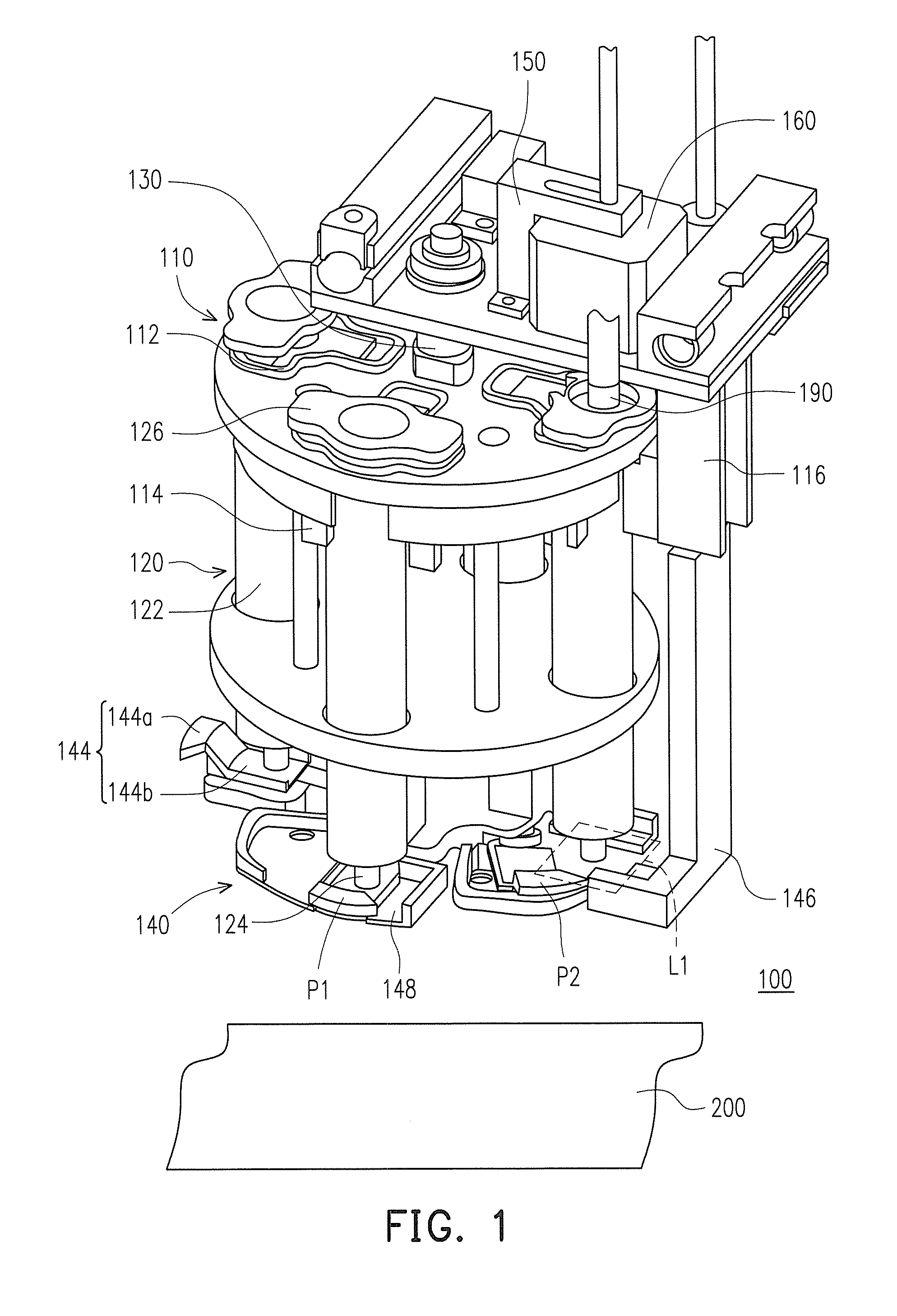
[0016]FIG. 1 is a schematic view of printing head module according to an exemplary embodiment. Referring to FIG. 1, in the present embodiment, a printing head module 100 is applicable to a three-dimensional (3-D) printing apparatus for printing a 3-D object on the base 200...


PUM


Abstract

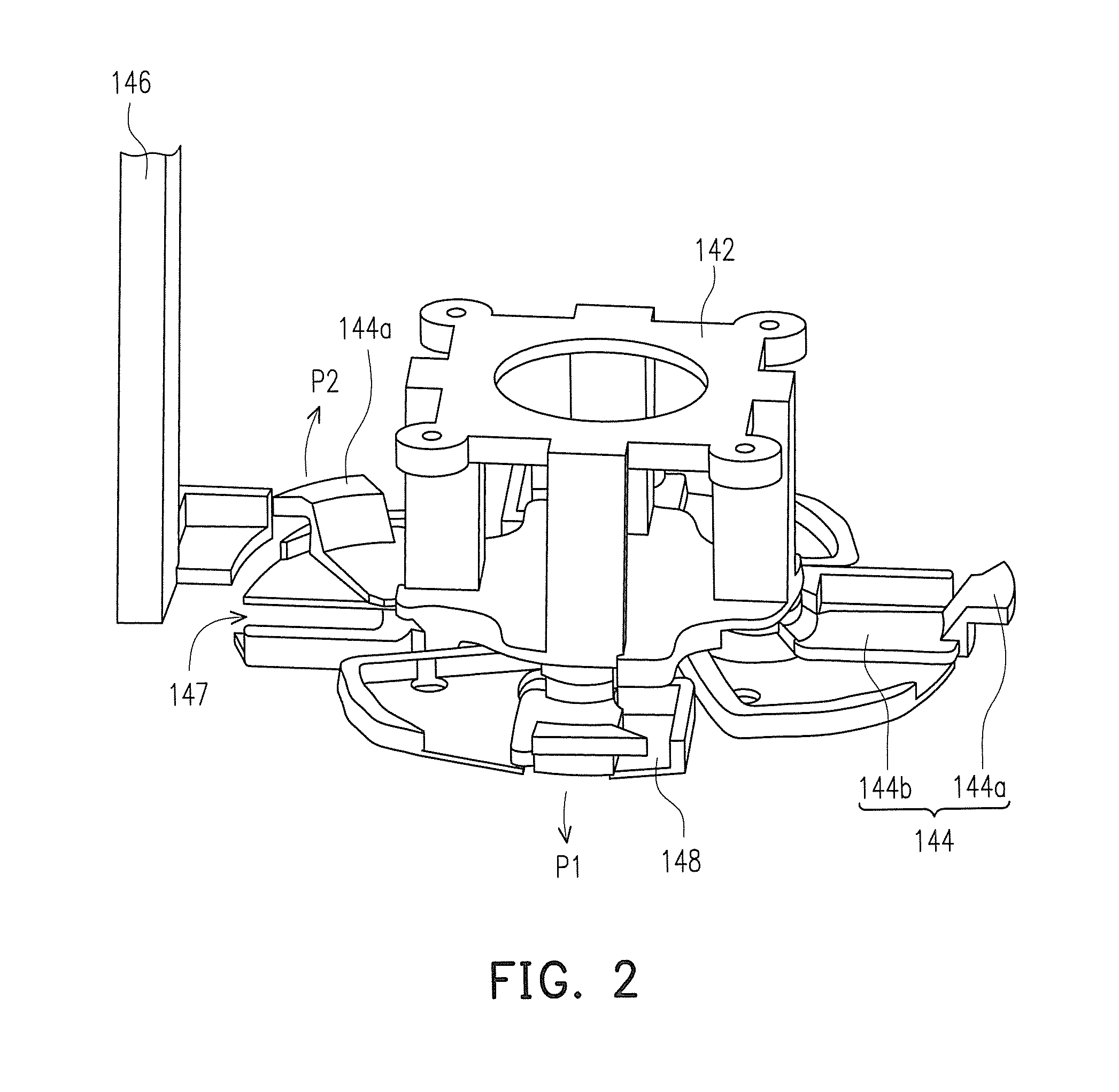
A printing head module includes a bracket, a plurality of printing heads, a pivot shaft, a wiper unit, and a control unit. The bracket includes a plurality of through holes. The printing heads are parallelly aligned with each other, each of the printing heads a nozzle for extruding the modeling material. The pivot shaft connected to the bracket is adapted to rotate the printing heads to a target position. The wiper unit includes a holder, a plurality of wipers, and a wiper opener. The holder is connected to the pivot shaft to be rotated with the bracket and the printing heads. The wipers rotatably connected to the holder and disposed correspondingly to the openings. The wiper opener is disposed at the target position to interfere with the wiper rotated to the target position, so as to drive the corresponding wiper to rotate to the opening position.

Description

BACKGROUND OF THE INVENTION[0001]1. Technical Field[0002]The technical field relates to a printing head module, and more particularly to a printing head module having a wiper unit.[0003]2. Description of Related Art[0004]With advancement in computer-aided manufacturing (CAM), a three dimensional printing technology (3-D printing technology) has been developed in the manufacturing industry, thereby rapidly fabricating products from an original design concept. The 3-D printing, in fact, is a general term of a series of rapid prototyping (RP) techniques, and the basic principle thereof, and the concept thereof is a laminate manufacturing, wherein a rapid prototyping machine is used to form cross-sectional shapes of a workpiece in the X-Y plane through scanning, shift intermittently at a layer thickness in the Z coordinates, and ultimately form 3-D objects. The 3-D printing technology is unrestrictedly applicable for the geometric shapes and the RP technology produces excellent outputs ...

Claims


Application Information

Patent Timeline
Patent Type & Authority Patents(United States)
IPC IPC(8): B41J2/165
CPCB41J2/16544B41J2/16535
Inventor DIN, SHIH-JERCHANG, JUI-FENGCORDERO, CLYDE VENTOLINA
Owner XYZPRINTING
Learn More