
Liquid discharging apparatus and liquid discharging method

a liquid discharging apparatus and liquid discharging technology, applied in the direction of color measuring devices, typewriters, textiles and paper, etc., can solve the problems of not being able to substitute fabrics with other fabrics, not being able to achieve uniform forming of desired colors in color management systems, and not being able to achieve the effect of reducing the effect of recording medium coloring

Active Publication Date: 2016-03-08
SEIKO EPSON CORP
View PDF9 Cites 2 Cited by
  • Summary
  • Abstract
  • Description
  • Claims
  • Application Information

AI Technical Summary

Benefits of technology

Enables convenient and stable printing with desired coloration, reducing labor and production time by eliminating the need for pre-prepared data for each fabric type and effectively handling color variations and irregularities.

Problems solved by technology

On the other hand, since fabric as a recording medium is a material which is a fiber product such as clothing which is different to recording media where quality is managed under constant standards such as paper, film, or the like which are media for recording images or information, there are various recording characteristics such as the permeability and color development property of inks according to the fabric material, surface texture, and color and there are numerous fabrics where it is difficult to consistently perform forming of desired colors in a color management system which is provided in an ink jet printer in advance.
However, there is a problem in that it is not possible to substitute fabrics with other fabrics where only the recording characteristics are superior since there are characteristics, such as individual value and sense of feel with the fabric itself which is different to paper or films as the material which is a fiber product.
In addition, there is also a problem in that there are also numerous fabrics where it is not possible with deal with variations in color, color irregularities, and the like in types of desired fabrics in data which is prepared in advance.

Method used


Image

  • Liquid discharging apparatus and liquid discharging method
  • Liquid discharging apparatus and liquid discharging method
  • Liquid discharging apparatus and liquid discharging method

Examples


first embodiment

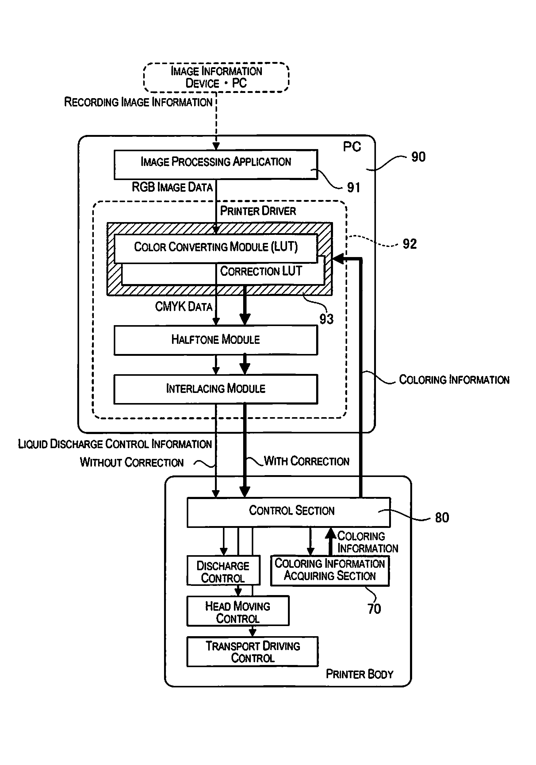
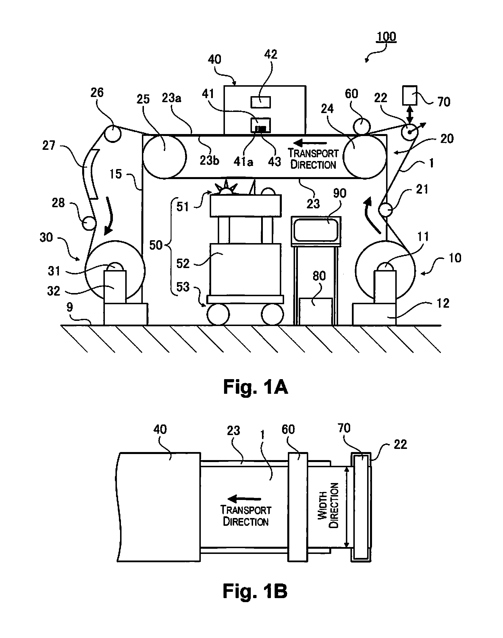
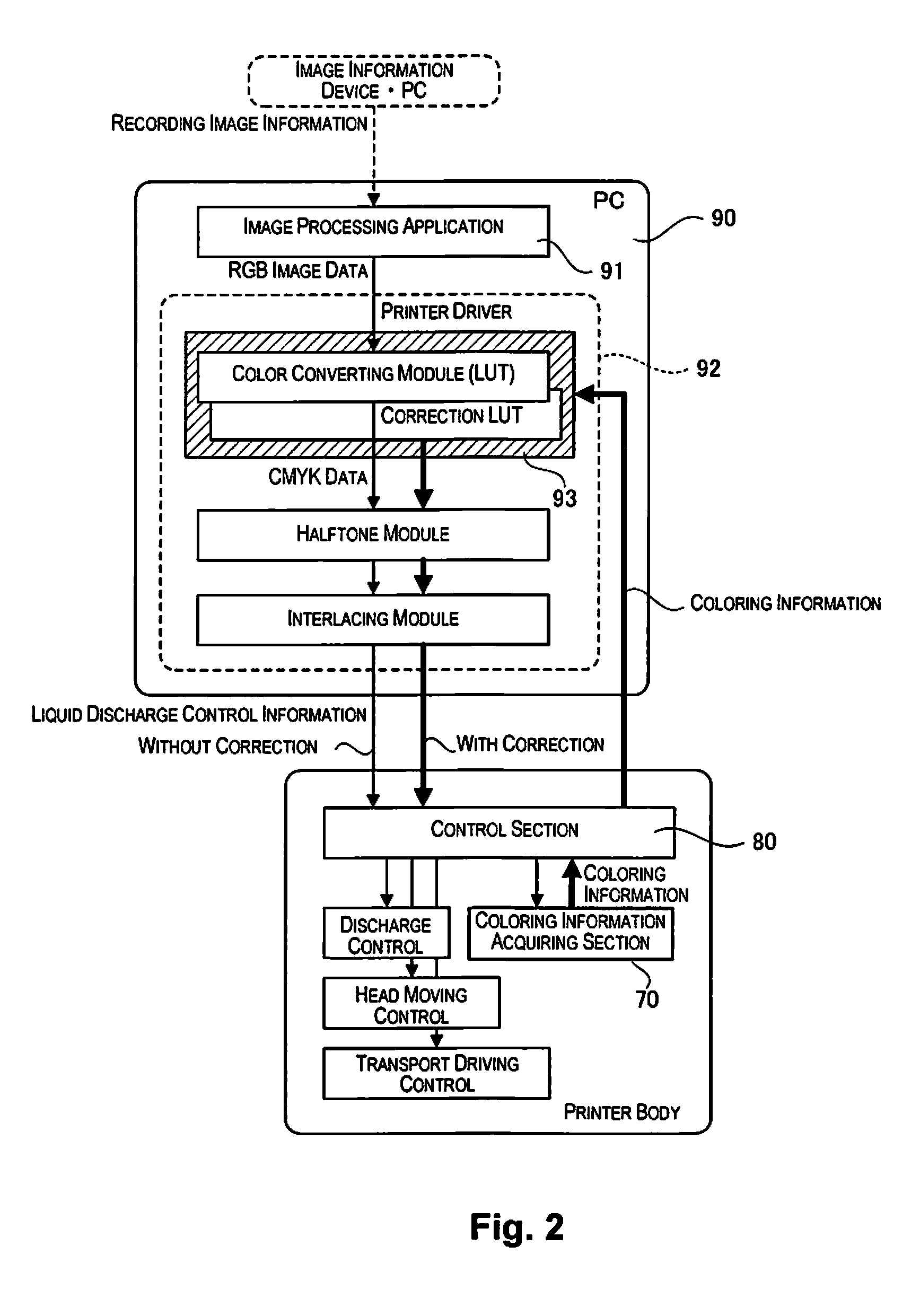
[0066]FIG. 1A is a schematic diagram illustrating a textile printing apparatus 100 as a “liquid discharging apparatus” according to a first embodiment and FIG. 1B is a planar diagram illustrating arranging of a coloring information acquiring section. FIG. 1A illustrates the textile printing apparatus 100, which is installed on a floor surface, from a side surface and FIG. 1B illustrates arranging of a coloring information acquiring section, which is provided in the textile printing apparatus 100, from the upper surface.

[0067]The textile printing apparatus 100 is a liquid discharging apparatus which performs textile printing on a fabric 1 by forming (recording) an image by discharging ink as a “liquid” onto the fabric 1 as a “recording medium”.

[0068]The textile printing apparatus 100 has a fabric supply section 10 as a “supply section”, a fabric transport section 20 as a “transport section”, a fabric collecting section 30, an ink jet section 40 as an “image forming section”, a mainte...

modified example 1

[0130]FIGS. 3A and 3B are schematic diagrams illustrating variations in installation positions and configurations of the coloring measuring section 70 in the textile printing apparatus 100 as a modified example 1.

[0131]The coloring measuring section 70 is described in the first embodiment as being installed at the position of the tension roller 22 as shown in FIGS. 1A and 1B, but the configuration is not limited to this configuration, and there may be a configuration where, for example, the coloring measuring section 70 is installed at positions of each of coloring measuring sections 70a, 70b, 70c, and 70d as shown in FIGS. 3A and 3B.

[0132]The coloring measuring section 70a is arranged at a position where it is possible to measure the fabric 1 which is held on the transport belt 23, in detail, at a position on the transport path where the fabric 1 is measured at the region where the fabric 1 is held by the support surface 23a where the adhesive layer is provided as the “holding sect...

modified example 2

[0141]FIGS. 4A and 4B are schematic diagrams illustrating variations in installation positions and configurations of the coloring measuring section 70 in the textile printing apparatus 100 as a modified example 2.

[0142]The coloring measuring section 70 is described in the first embodiment as being arranged so as to cover the entirety of the width direction of the fabric 1 at the position of the tension roller 22 as shown in FIG. 1B, but the configuration is not limited to this configuration and the position or the configuration of the coloring measuring section 70e which are shown in FIGS. 4A and 4B may be used.

[0143]The coloring measuring section 70e is moved integrally with the head 41 by the head moving section 42. In detail, whereas the coloring measuring section 70 in the first embodiment is configured using, for example, a line sensor, which is arranged so as to cover the entirety of the width direction of the fabric 1, the coloring measuring section 70e uses a smaller line se...


PUM

PropertyMeasurementUnit
tensionaaaaaaaaaa
coloraaaaaaaaaa
permeabilityaaaaaaaaaa

Abstract

A liquid discharging technique is provided that conveniently carries out recording (printing) with a desired coloring relative to media (fabric or the like) with various characteristics such as an ink color development property. A textile printing apparatus 100 is a liquid discharging apparatus which discharges a liquid (an ink) onto a recording medium (a fabric 1) and records an image and includes a liquid discharging section (a head 41) which discharges the ink onto the fabric 1 based on correction image information which is corrected according to coloring information for the fabric 1 which is obtained from the fabric 1 which is supplied to the textile printing apparatus 100.

Description

CROSS-REFERENCE TO RELATED APPLICATIONS[0001]This application claims priority to Japanese Patent Application Nos. 2013-173037 filed on Aug. 23, 2013 and 2013-173038 filed on Aug. 23, 2013. The entire disclosures of Japanese Patent Application Nos. 2013-173037 and 2013-173038 are hereby incorporated herein by reference.BACKGROUND[0002]1. Technical Field[0003]The present invention relates to a liquid discharging apparatus and a liquid discharging method.[0004]2. Related Art[0005]An ink jet printer which performs recording (printing) of images by discharging ink droplets onto various types of recording media such as paper or film is known as an example of a liquid discharging apparatus. Since it is easy for ink jet printers to record digital color images in high definition, their use rapidly became widespread in a wide range of fields from office use and personal use to industrial uses. The targets of the recording also widened to various media which are used in various fields, and app...

Claims


Application Information

Patent Timeline
Patent Type & Authority Patents(United States)
IPC IPC(8): B41J2/21D06P5/30D06P1/00B41J3/407B41J11/00G01J3/50
CPCB41J2/2132B41J3/4078B41J11/009D06P1/0032D06P5/30G01J3/50
Inventor HAYAFUCHI, YUYA
Owner SEIKO EPSON CORP
Learn More