Optical writing head and image forming apparatus

an image forming apparatus and writing head technology, applied in the field of optical writing head and image forming apparatus, can solve the problems of unfavorable image quality control, and high cost of optical writing head, and achieve the effect of low cost and simple configuration

Inactive Publication Date: 2016-03-08
CANON KK
View PDF16 Cites 2 Cited by
  • Summary
  • Abstract
  • Description
  • Claims
  • Application Information

AI Technical Summary

Benefits of technology

[0014]In view of the above-identified problem, the present invention provides an optical writing head, as well as an image forming apparatus, having a simple configuration that can be assembled at low cost, unlike that of the prior art, without requiring any accurate alignment of the light emitting device array and the rod lens array thereof.
[0017]According to the present invention, an optical writing head having a simple configuration and an image forming apparatus including such an optical writing head can be realized at low cost, unlike the prior art, without requiring any accurate alignment of the light emitting device array and the rod lens array thereof.

Problems solved by technology

Then, as a result, an uneven density and color changes appear on the recorded image.
The known technique in the '306 patent is provided to reduce the color change by making the shapes of the light spots of the component colors change to show the same shape and, hence, is accompanied by a problem as described below.
This makes the optical writing head costly.

Method used


Image

  • Optical writing head and image forming apparatus
  • Optical writing head and image forming apparatus
  • Optical writing head and image forming apparatus

Examples


example 1

[0058]An optical writing head according to the present invention and having a configuration as described below by referring to FIGS. 5A to 5D was prepared in Example 1.

[0059]A grating 102 as shown in FIGS. 5A and 5B was used in the optical writing head 100 of this Example.

[0060]FIG. 5A is a top plan view of the grating 102 and FIG. 5B is a cross-sectional view taken along line 5B-5B in FIG. 5A.

[0061]The grating 102 is of a structure showing a periodic refractive index distribution produced by an aperture portion 501 and a background portion 502 on a substrate 506.

[0062]The background portion 502 and the aperture portion 501 are formed by respective transparent materials whose refractive indexes differ from each other. For example, the aperture portion 501 may be formed by air, while the peripheral portion 502 may be formed by a dielectric material such as quartz.

[0063]Of the grating 102 of this example, the aperture portion 501 is formed by air and the apertures thereof have a width...

example 2

[0084]An optical writing head using a grating 102 that is different from the grating of Example 1, and can be prepared more easily, will be described below by referring to FIGS. 6A to 6D.

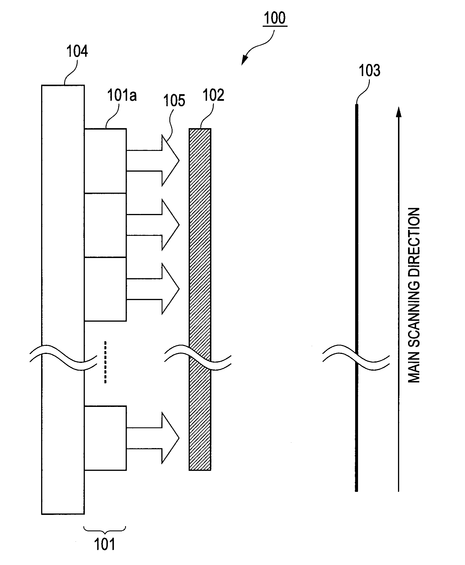
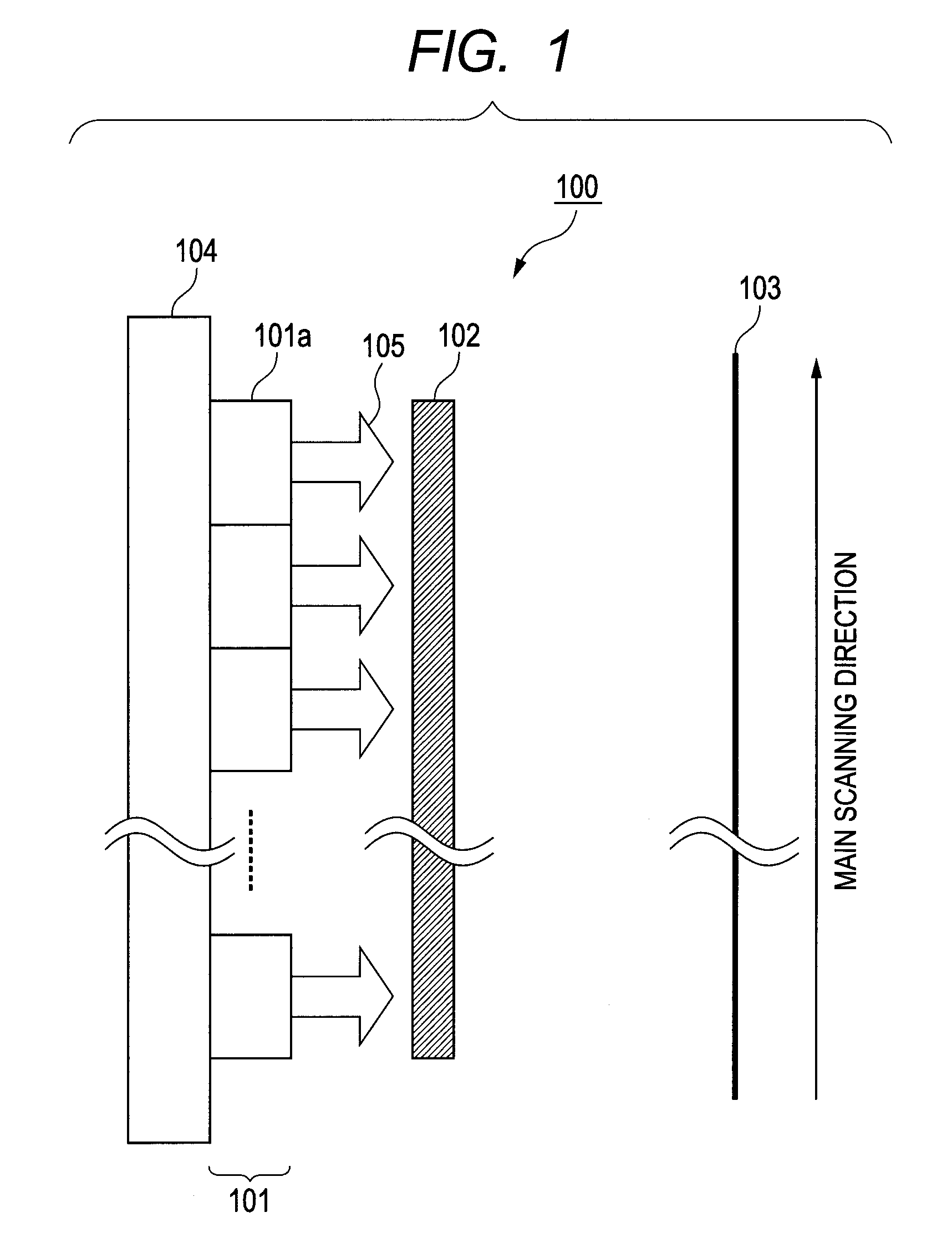
[0085]The optical writing head 100 of this example has the same configuration us that of the one shown in FIG. 1, and the grating 102 thereof is formed by arranging square apertures, respectively, at the lattice points of a square grating.

[0086]FIG. 6A is a top view of the grating 102 that includes a background portion 602 and an aperture portion 601.

[0087]FIG. 6B is a cross-sectional view of the grating 102 taken along line 6B-6B in FIG. 6A. As shown in FIG. 6B, the grating 102 is arranged on a transparent substrate 606.

[0088]The background portion 602 is required only to have a characteristic of reflecting and / or absorbing light emitted from light emitting device array 101 so as not to transmit light. The background portion 602 may typically be formed by means of metal, such as silver.

[0089]The tr...


PUM


Abstract

An optical writing head includes a light emitting device array having a plurality of light emitting device that emit parallel rays of light, and an optical unit arranged between the light emitting device array and an image plane to form an image by the rays of light emitted from the light emitting devices on the image plane. The optical unit includes a two-dimensional grating.

Description

CLAIM OF PRIORITY[0001]This application claims the benefit of Japanese Patent Application No. 2011-047245, filed Mar. 4, 2011, which is hereby incorporated by reference herein in its entirety.BACKGROUND OF THE INVENTION[0002]1. Field of the Invention[0003]The present invention relates to an optical writing head and an image forming apparatus. More particularly, the present invention relates to an optical writing head designed to cause a plurality of light emitting devices to project rays of light onto a target irradiation surface by means of a lens array to form image formation spots, and an image forming apparatus using the same. Such an optical writing head finds applications in the fields of electrophotographic copying machines, printers, and facsimile machines.[0004]2. Description of the Related Art[0005]Known optical writing heads to be used in electrophotographic copying machines include an array of light emitting devices, such as LEDs, and a rod lens array formed by arranging...

Claims


Application Information

Patent Timeline
Patent Type & Authority Patents(United States)
IPC IPC(8): B41J2/47B41J2/45
CPCB41J2/451
Inventor NOBAYASHI, KAZUYA
Owner CANON KK
Why Eureka
Try Eureka