Parallel power supply and power detection method for parallel power supply

a power detection method and parallel power supply technology, applied in the field of parallel power supply and power detection methods, can solve the problems of increasing the risk of damaging data on the client side or damaging the system, system damage, test engineer may not have suitable fixtures, etc., and achieves the effect of easy determination of the quality of the power supply through a display/audio uni

Active Publication Date: 2016-03-08
3Y POWER TECH TAIWAN
View PDF4 Cites 1 Cited by
  • Summary
  • Abstract
  • Description
  • Claims
  • Application Information

AI Technical Summary

Benefits of technology

[0008]The proposed parallel power supply includes a built-in test switch so that the power detection may be performed without inserting the proposed parallel power supply into a system or a fixture. Hence, an internal operation of the power supply may be clarified quickly, and almost no extra cost is required. In addition, a test engineer can readily determine quality of a power supply through a display / audio unit merely by adding a test switch inside the power supply.

Problems solved by technology

If the parallel power supply has a serious electrical problem, the insertion, however, may increase the risk of damaging data on the client side or damaging the system.
If the parallel power supply is inserted into and pulled out of the system frequently, the system may be damaged.
The test engineer may have no suitable fixtures.

Method used


Image

  • Parallel power supply and power detection method for parallel power supply
  • Parallel power supply and power detection method for parallel power supply
  • Parallel power supply and power detection method for parallel power supply

Examples


Embodiment Construction

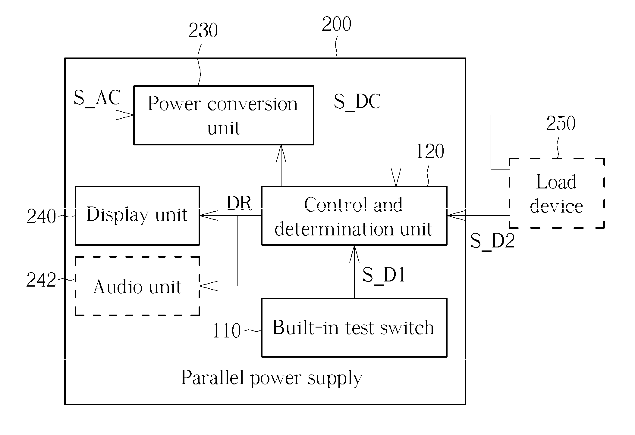
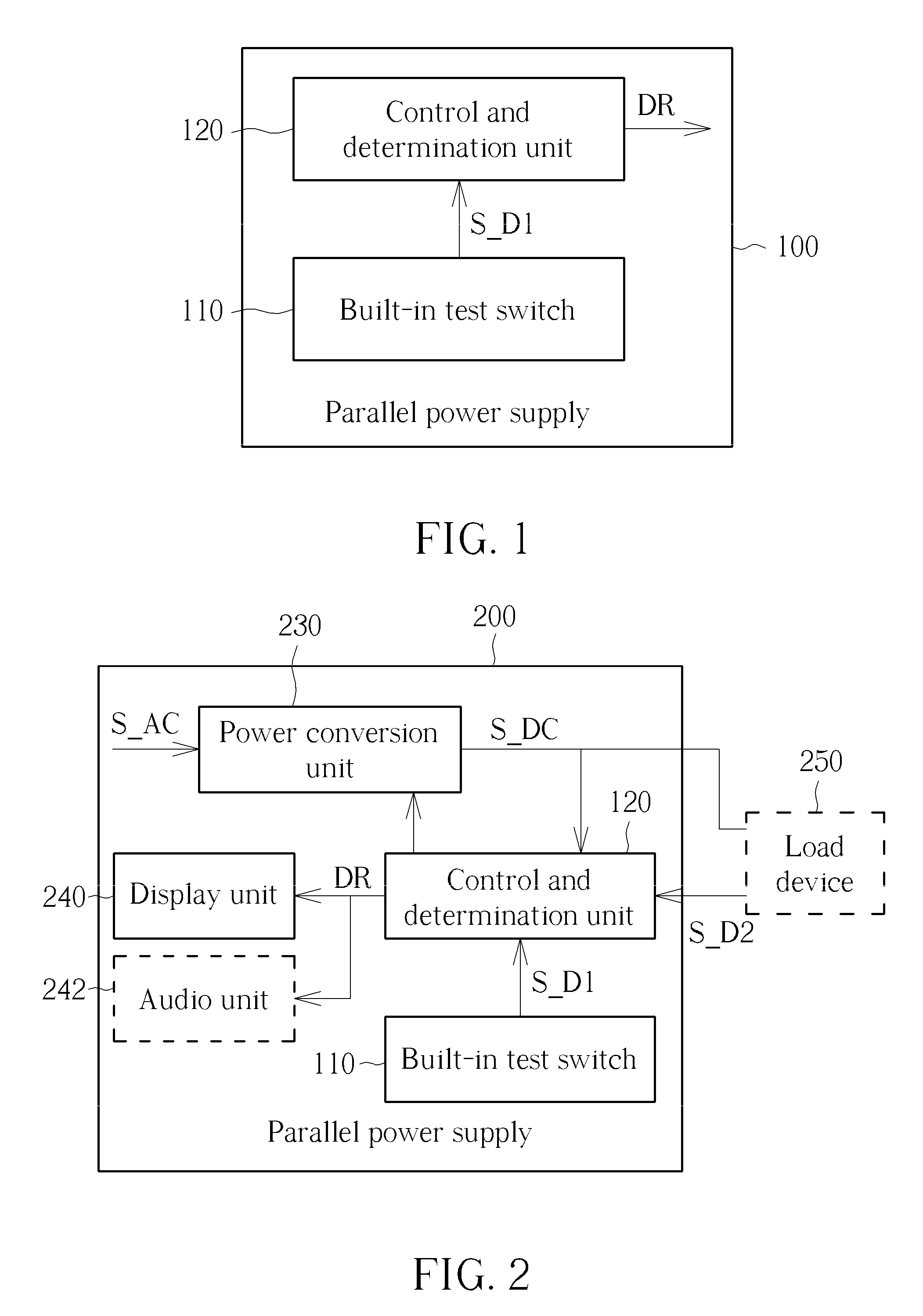
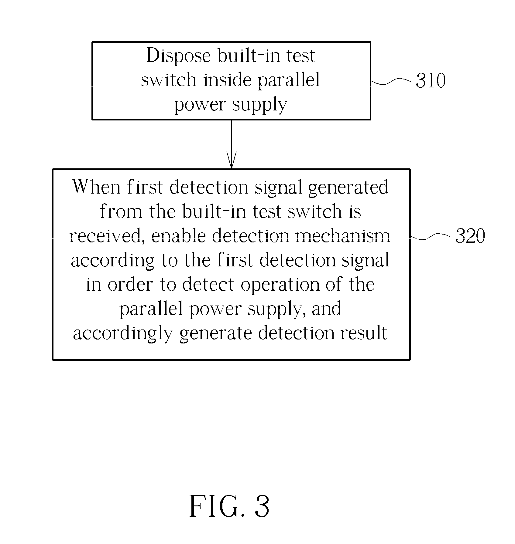
[0014]Please refer to FIG. 1, which is a diagram illustrating an exemplary parallel power supply according to an embodiment of the present invention. The parallel power supply 100 includes, but is not limited to, a built-in test switch 110 and a control and determination unit 120. As shown in FIG. 1, the built-in test switch 110 is arranged to generate a first detection signal S_D1. The control and determination unit 120 is coupled to the built-in test switch 110. When receiving the first detection signal S_D1, the control and determination unit 120 is operative for enabling a detection mechanism according to the first detection signal S_D1 in order to detect an operation of the parallel power supply 100, and accordingly generating a detection result DR. For example, the built-in test switch 110 may be a key switch. When the key switch (i.e. the built-in test switch 110) is pressed, the control and determination unit 120 may receive the first detection signal S_D1 and enable the det...


PUM


Abstract

A parallel power supply includes a built-in test switch and a control and determination unit. The built-in test switch is arranged to generate a first detection signal. The control and determination unit is coupled to the built-in test switch. When receiving the first detection signal, the control and determination unit is operative for enabling a detection mechanism according to the first detection signal in order to detect an operation of the parallel power supply, and accordingly generating a detection result. A power detection method for a parallel power supply includes: disposing a built-in test switch inside the parallel power supply; and when receiving a first detection signal generated from the built-in test switch, enabling a detection mechanism according to the first detection signal in order to detect an operation of the parallel power supply, and accordingly generating a detection result.

Description

BACKGROUND OF THE INVENTION[0001]1. Field of the Invention[0002]The disclosed embodiments relate to a power supply, and more particularly, to a parallel power supply which does not need to be inserted into a system or a fixture for power detection, and a related power detection method thereof.[0003]2. Description of the Prior Art[0004]A parallel power supply (e.g. a redundant power supply) conventionally needs to be inserted into a load device (e.g. a system or a fixture) in order to determine whether the parallel power supply operates normally. For example, a test engineer may use a fixture to detect a parallel power supply assembled on a production line for yield management. In a server room, a system engineer needs to insert the parallel power supply into a system to promptly determine whether the parallel power supply operates normally. If the parallel power supply has a serious electrical problem, the insertion, however, may increase the risk of damaging data on the client side...

Claims


Application Information

Patent Timeline
Patent Type & Authority Patents(United States)
IPC IPC(8): H02M7/5383G05F3/00H02J1/10G01R31/40
CPCG05F3/00H02J1/10G01R31/40
Inventor TSAI, CHIH-CHANG
Owner 3Y POWER TECH TAIWAN
Why Eureka
Try Eureka