
Programmable logic controller-based control center and user interface for air sampling in controlled environments

a control center and logic controller technology, applied in the direction of program control, electric programme control, instruments, etc., can solve the problems of difficult and expensive customization or change, and the possibility of human health health threats

Active Publication Date: 2016-03-15
VALTEK ASSOC INC
View PDF48 Cites 10 Cited by
  • Summary
  • Abstract
  • Description
  • Claims
  • Application Information

AI Technical Summary

Benefits of technology

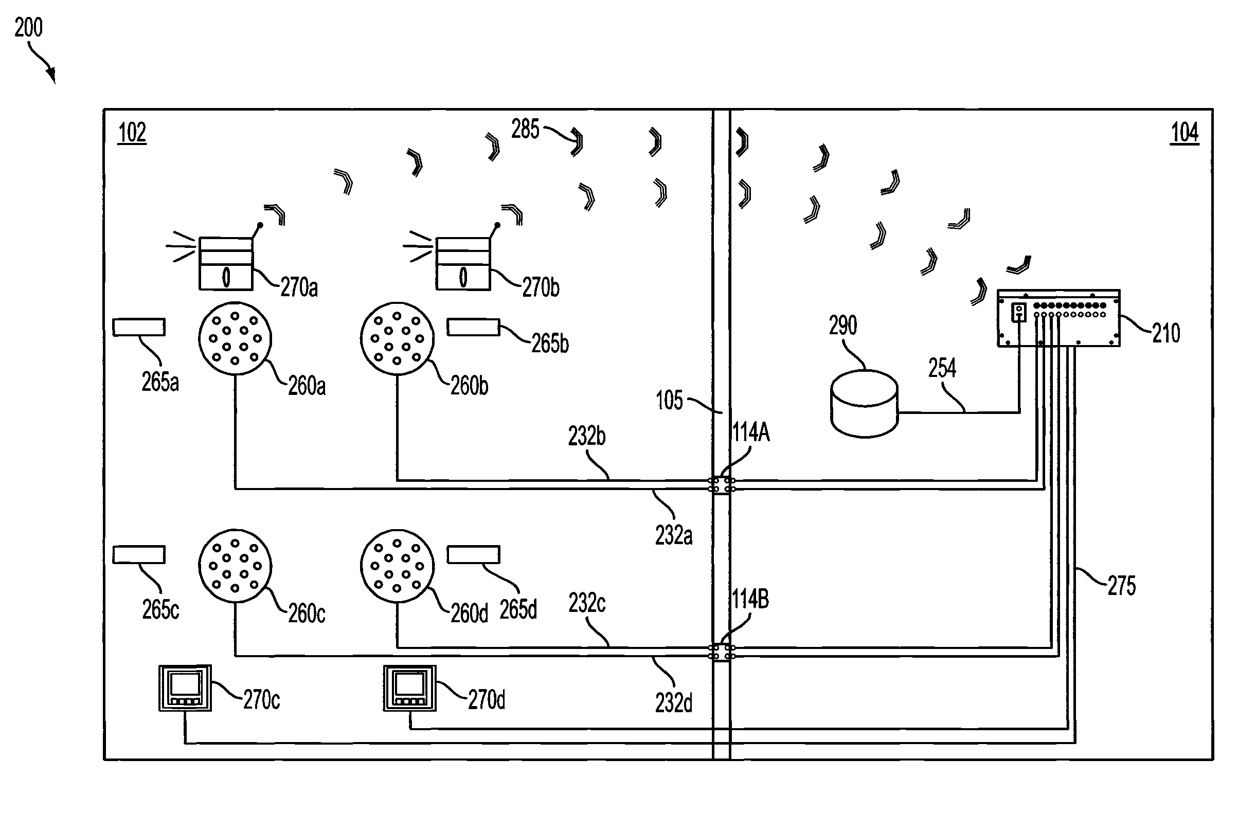
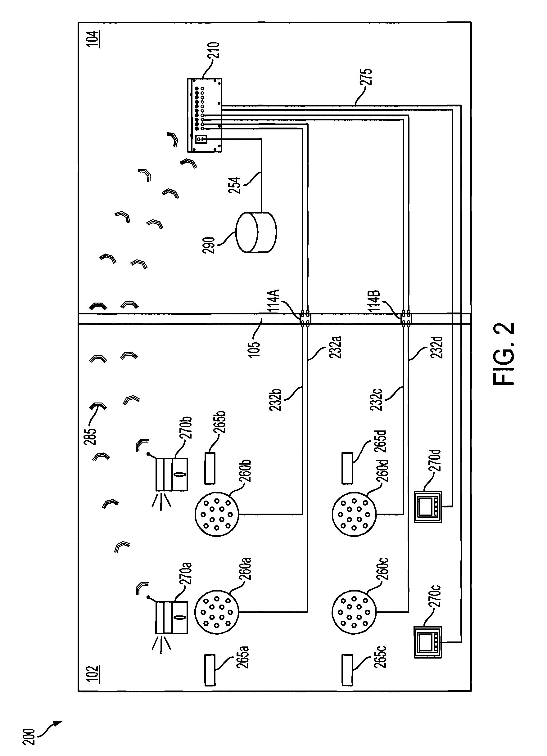
[0062]It is appreciated that one advantage of the present invention includes simplifying the configuration of the air sampling devices and related components necessary for monitoring and controlling air sampling in a controlled environment by avoiding the need for certain components, such as conventional flow switches. The present invention also provides a high degree of flexibility to rearrange a display to show any number of individual parameters associated with air sampling and monitoring including, but not limited to, the location name, sample time, or duration of air quality tests. Because conventional devices are not PLC-based and therefore are not programmable, as new features are created, physical changes to the hardware are required and do not allow for the collection of time sample data. The present invention overcomes these shortcomings by providing a flexible, programmable air sampling and monitoring system that includes a programmable logic controller-based control center and a plurality of associated touch panel displays sharing a unified interface.

Problems solved by technology

However, that is not always the case, as other operations within those industries may generate contaminants that are above acceptable levels and, therefore, must be prevented from escaping the clean room without treatment.
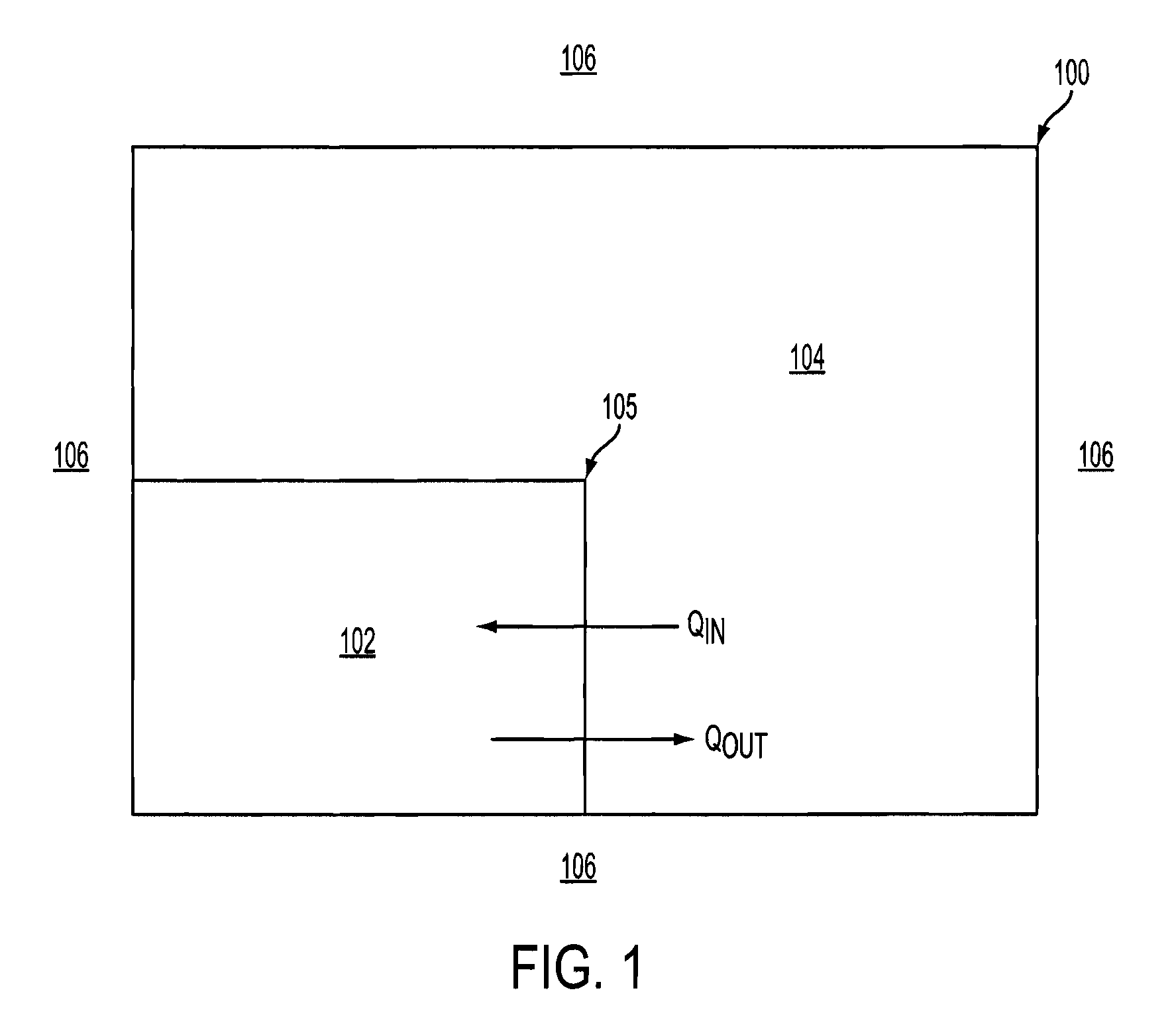
Negative pressure rooms are often used when there is a concern that contaminants in the air in the room may pose a potential health threat to human health in adjacent spaces or the environment.
A disadvantage associated with conventional air sampling systems is that, because the HCI is hardware-based, it is often difficult and expensive to customize or change.

Method used


Image

  • Programmable logic controller-based control center and user interface for air sampling in controlled environments
  • Programmable logic controller-based control center and user interface for air sampling in controlled environments
  • Programmable logic controller-based control center and user interface for air sampling in controlled environments

Examples


Embodiment Construction

[0014]None of the conventional devices described above provide a high degree of flexibility to rearrange a display to show any number of individual parameters associated with air sampling and monitoring including, but not limited to, the location name, sample time, or duration of air quality tests. Because these conventional devices are not programmable, as new features are created, physical changes to the hardware are required. Additionally, none of the conventional devices described above allow for the collection of time sample data. The present invention overcomes these shortcomings by providing a flexible, programmable air sampling and monitoring system that includes a programmable logic controller-based control center and a plurality of associated touch panel displays sharing a unified interface.

[0015]The present invention will be explained in terms of exemplary embodiments. This specification discloses one or more embodiments that incorporate the features of this invention. Th...


PUM


Abstract

In accordance with an aspect of the present invention there is provided a system for sampling air at multiple locations in a controlled environment. The system includes one or more air sampling devices configured to monitor and test a volume of air within a controlled environment. A control center including a programmable logic controller (PLC) is configured to monitor and control the one or more air sampling devices. One or more touch panel displays are connected to the control center and provide a human-computer interface between the control center and users.

Description

FIELD OF INVENTION[0001]The present invention relates to devices and methods for monitoring airborne contaminants. In particular, the present invention relates to a programmable logic controller-based control center and corresponding human computer interface for controlling air sampling in controlled environments.BACKGROUND OF THE INVENTION[0002]Clean rooms found in manufacturing, research, and other facilities are typically classified into two broad categories based on the static air pressure inside the rooms relative to atmospheric pressure and / or based on the air pressure in spaces adjacent the clean rooms. A positive air pressure room is maintained at an absolute air pressure greater than atmospheric pressure, greater than the air pressure in spaces adjacent the clean room, or both. The positive air pressure in such rooms is provided by pumping filtered and / or conditioned air into the rooms and controlling the flow of air out of the rooms. The adjacent spaces, which may be manuf...

Claims


Application Information

Patent Timeline
Patent Type & Authority Patents(United States)
IPC IPC(8): G08B21/00G05B19/02G01M3/28G08B21/12
CPCG05B19/02G01M3/2815G08B21/12G08B25/009G08B25/14G01N33/0063G01N33/0073G01N1/2273G05B19/058G05B2219/13031
Inventor CHURCHVARA, JEFFREYPHILLIPS, MARK
Owner VALTEK ASSOC INC
Learn More