Single layer 3D tracking semiconductor detector

a semiconductor detector and single-layer technology, applied in the field of pixel detectors, can solve the problems of providing two-dimensional information of radiation fields, and achieve the effects of simple and affordable means, moderate power consumption of pixel detectors, and robustness

Active Publication Date: 2016-03-29
CZECH TECH UNIV IN PRAGUE
View PDF7 Cites 25 Cited by
  • Summary
  • Abstract
  • Description
  • Claims
  • Application Information

AI Technical Summary

Benefits of technology

[0012]Note that in gas detectors, drift times have in the past already been accounted for in the construction of event locations based on arrival time measurements. These devices have been referred to as “time projection chambers”. In gas detectors, charges of single electrons are amplified prior to detection. In the typical application, a high energy particle liberates single electrons from gas atoms as it crosses the gas volume. The electrons drift in an electric field in the gas volume and are amplified in a high field strength area above the read-out electronic such as to electron charge avalanches that can be detected. However, in gas detectors, drift times are much longer than in a single semiconductor layer which makes three-dimensional reconstruction more straightforward.
[0025]The output of said XOR gate is preferably connected with a device for measuring the time span during which the output of the XOR gate is “true”, which corresponds to the time delay between the arrival of signals at neighbouring read-out circuits. While these time spans will be very short, again no fast clock is necessary for measuring this time span. Instead, the output of the XOR gate may e.g. be connected with a capacitor charged while the output of the XOR gate is “true”. The charge accumulated on the capacitor is a measure for the time span, hence providing quantitative timing information.
[0026]An alternative means for measuring the arrival time difference between neighbouring pixels could be based on a design in which a local oscillator is started when one pixel is hit and stopped when the neighbouring pixel is hit. The output of the oscillator would be connected to a fast counter and its content would be a measure of the delay. Clearly, this embodiment would be more power consuming than charging a capacitor. Nevertheless, unlike providing a global fast clock, this embodiment would only consume power when a particle is actually being detected. Accordingly, this demonstrates how restriction to relative time measurements between neighbouring pixels allows for power saving, even if a fast clock or counter is not entirely dispensed with.
[0033]As is apparent from the above discussion, the new pixel detector allows for obtaining 3-dimensional information employing only a single semiconductor sensor layer, and it does so without requiring a global fast clock or actually any fast clock at all. Herein, a “fast clock” is a clock that would allow resolving relevant drift time differences due to particle trajectories that are inclined with regard to the X-Y-plane. By dispensing with such “fast clock”, the power consumption of the pixel detector can be kept very moderate.
[0034]With these advantages, the new pixel detector should find many important applications. For example, the pixel detector would be ideally suited for use in a Compton camera. A Compton camera allows to reconstructing γ-ray emitting radio isotope distributions based on electrons generated due to Compton scattering. For this, clearly three-dimensional information about the γ particle and / or Compton electron trajectories is necessary. With the pixel detector of the invention, this can be obtained with robust, simple and affordable means. This is believed to be particularly attractive for use in Compton cameras employed in nuclear medicine diagnosis devices, and in particular in a SPECT device. However, a Compton camera employing the pixel detector of the invention could also be very advantageously employed in a device for monitoring decommissioning of nuclear power plants.

Problems solved by technology

While such pixel detectors offer remarkable advantages with regard to robustness, sensitivity and versatility, by construction they can only provide two-dimensional information of a radiation field.

Method used


Image

  • Single layer 3D tracking semiconductor detector
  • Single layer 3D tracking semiconductor detector
  • Single layer 3D tracking semiconductor detector

Examples


Embodiment Construction

[0040]For the purposes of promoting an understanding of the principles of the invention, reference will now be made to the preferred embodiment illustrated in the drawings and specific language will be used to describe the same. It will nevertheless be understood that no limitation of the scope of the invention is thereby intended, such alterations and further modifications in the illustrated device and method and such further applications of the principles of the invention as illustrated therein being contemplated therein as would normally occur now or in the future to one skilled in the art to which the invention relates.

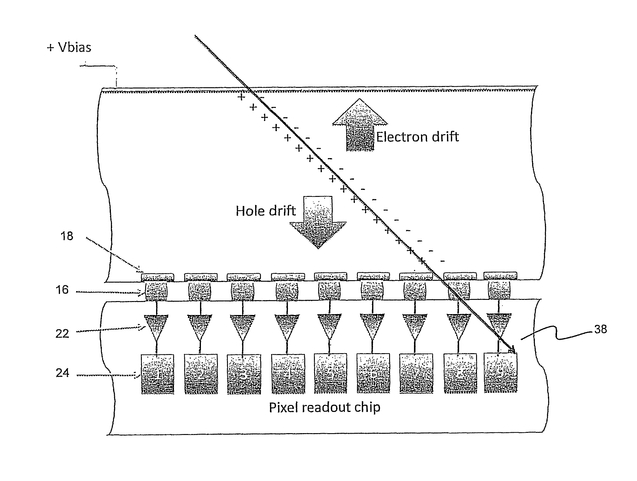
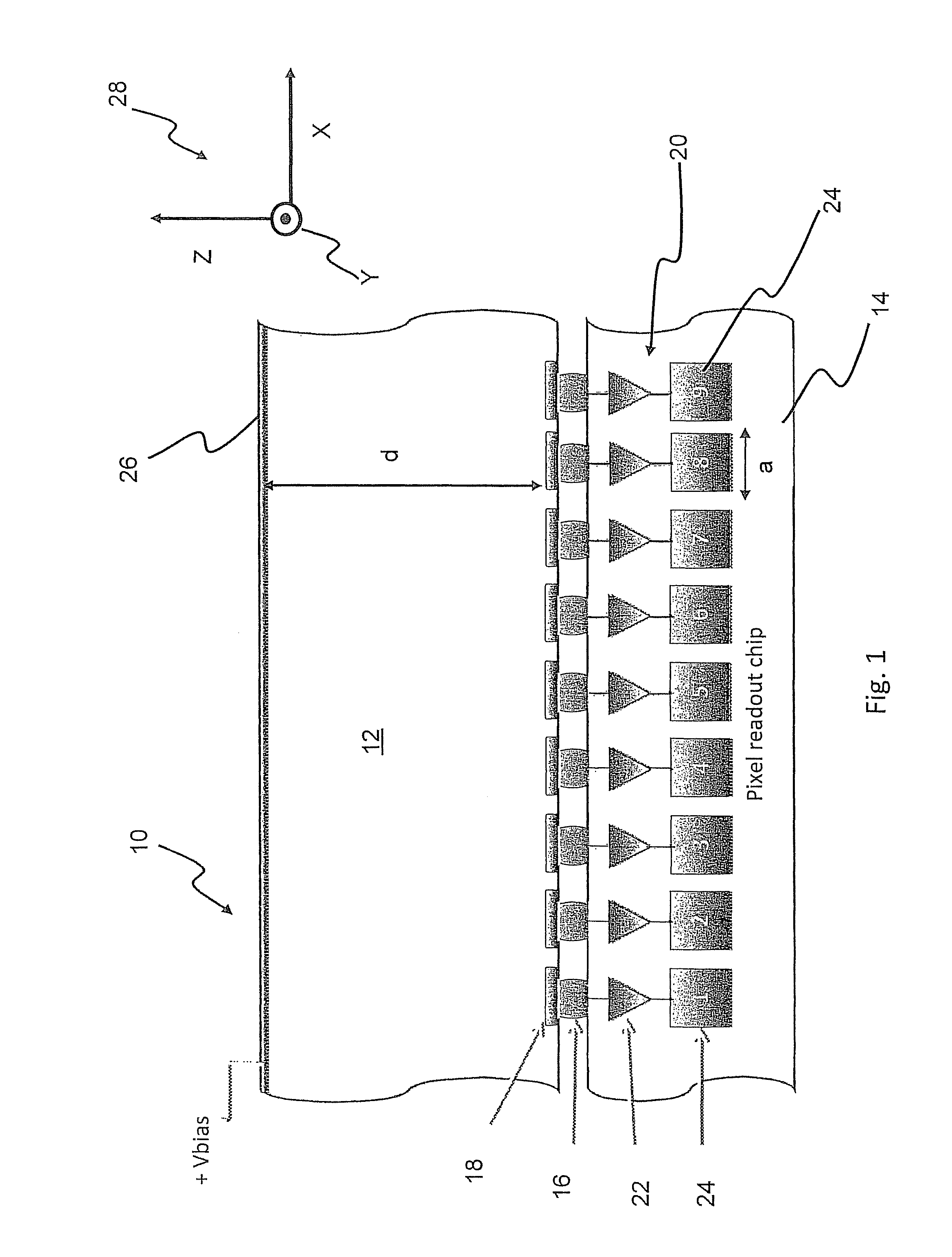
[0041]FIG. 1 is a sectional view of a pixel detector 10 according to an embodiment of the present invention. The pixel detector 10 comprises a semiconductor sensor layer 12, which in the present example is comprised of silicon. The pixel detector 10 further comprises a read-out electronics layer formed by a pixel read-out chip 14. The pixel read-out chip 14 is bon...


PUM


Abstract

The present invention relates to a pixel detector (10), comprising a semiconductor sensor layer (12), in which charges can be generated upon interaction with particles to be detected. The semiconductor layer defines an X-Y-plane and has a thickness extending in Z-direction. The detector further comprises a read-out electronics layer (14) connected to said semiconductor layer (12), said read-out electronics layer (14) comprising an array of read-out circuits (20) for detecting signals indicative of charges generated in a corresponding volume of said semiconductor sensor layer (12). The neighboring read-out circuits (20) are connected by a relative timing circuit configured to determine time difference information between signals detected at said neighboring read-out circuits (20). The time difference information is indicative of a difference in the Z-components of the locations of charge generations in the corresponding neighboring sensor volumes caused by a particle trajectory that is inclined with respect to the X-Y-plane.

Description

FIELD OF THE INVENTION[0001]The present invention is in the field of particle detecting devices. Herein, the term “particle” refers to any type of radiation quanta, including photons. In particular, the present invention relates to a pixel detector comprising a semiconductor sensor layer and a read-out electronics layer to the semiconductor layer.DESCRIPTION OF THE RELATED ART[0002]Pixel detectors according to the preamble of claim 1 are known from prior art. The pixel detector of the preamble of claim 1 comprises a semiconductor sensor layer in which charges can be liberated upon interaction with particles to be detected. Ionizing radiation produces free electrons and holes in the semiconductor material. The number of electron-hole pairs generated is proportional to the energy transmitted by the particle to the semiconductor material. The detector further comprises a read-out electronics layer electrically connected to the semiconductor layer. For example, the read-out electronics ...

Claims


Application Information

Patent Timeline
Patent Type & Authority Patents(United States)
IPC IPC(8): G01T1/24G01T1/29H01L27/146H01L31/115H01L31/08
CPCG01T1/2985G01T1/242G01T1/247G01T1/249H01L27/14661H01L31/085H01L31/115
Inventor CAMPBELL, MICHAELMICHEL, THILOJAKUBEK, JAN
Owner CZECH TECH UNIV IN PRAGUE
Why Eureka
Try Eureka