Smart module for communications, processing, and interface

a technology of communication, processing and interface, applied in the field of data collection and reporting system, can solve the problems of time-consuming and expensive change of main processing and reporting system, risk of failure of main environmental observation system, etc., and achieve the effect of convenient installation, minimal labor and material costs, and additional sensor capabilities

Inactive Publication Date: 2016-03-29
THE UNITED STATES OF AMERICA AS REPRESENTED BY THE SECRETARY OF THE COMMERCE
View PDF6 Cites 5 Cited by
  • Summary
  • Abstract
  • Description
  • Claims
  • Application Information

AI Technical Summary

Benefits of technology

[0027]The present invention provides a small, very low power, building block type module that may be used to interface new sensors, or conduct testing of new processing schemes without heavy system development, test, and costs typically encountered in modifying the larger more complex system. In addition, the small very low-power device contains core functions of data collection, processing, and communication. Thus, it can be repurposed to other uses, such as backup to other functions (e.g., GPS position reporting and environmental data transmission and control from shore). It contains readily available wireless communication components. Several of these devices may be organized into a wireless sensor and communications network.
[0030]The present invention has a number of applications and methods of use. In one embodiment, the device may be attached to a data buoy or other data collection system, to add additional sensor capabilities, without having to disturb existing sensor equipment. Existing data buoys are often designed as a sensor package, and if additional sensors were added to such a package, the entire system would need to be modified and tested to insure that the additional sensors and software does not create conflicts with other sensors. By providing a “stand alone” packaged sensor solution, the present invention may be readily installed in an existing data buoy, with minimal labor and materials costs, and without disturbing existing sensors, data processors, and communications systems.
[0031]The present invention has other applications as well, including as a back-up system, which may be readily installed when other systems fail. It may also be used to provide a back up locator if a data buoy fails or is dislodged. In a fail-safe mode, the system of the present invention can upload a GPS location to an IRIDIUM satellite every day for nearly three years, on battery power.
[0032]In addition, the device of the present invention may be used in a modular arrangement, where multiple devices may communicate with one another in wired or wireless modes. The device may be used as a Smart End Device, to log data from a sensor or sensors. Another device, communicating wirelessly or in wired mode, with one or more Smart End Devices, may serve as a Smart Coordinator, accumulating data from other Smart End Devices and uploading the packaged data via satellite modem. In order to reduce the number of different module types in the field, the smart modules of the present invention may be provided with similar or identical hardware, and then programmed in the field to act as Smart End Devices (logging data from sensors) and Smart Coordinators (accumulating data from Smart End Devices) and uploading the data via satellite. In this manner, the inventory of different device types is reduced, and redundant capabilities are provided in the field. If one smart module fails in whole or in part, another module may be configured, even remotely, to take over chores of the failed module.

Problems solved by technology

When new types of sensors, or processing schemes, are desired, changing the main processing and reporting system can be time-consuming and expensive because of the changes that are made to a complex system, and testing is required to check the changes and verify function of existing systems are not adversely impacted.
It also adds risk of failure to the main environmental observation system until a sufficient amount of testing, perhaps months to years, is completed.

Method used


Image

  • Smart module for communications, processing, and interface
  • Smart module for communications, processing, and interface
  • Smart module for communications, processing, and interface

Examples


Embodiment Construction

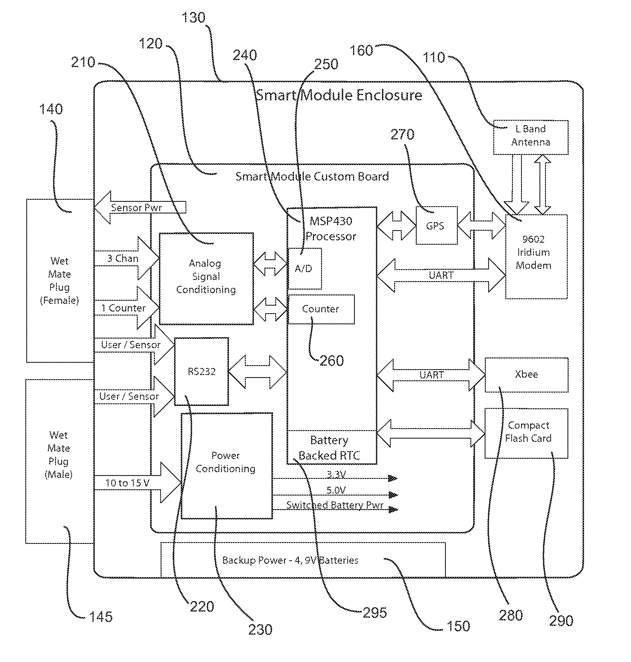
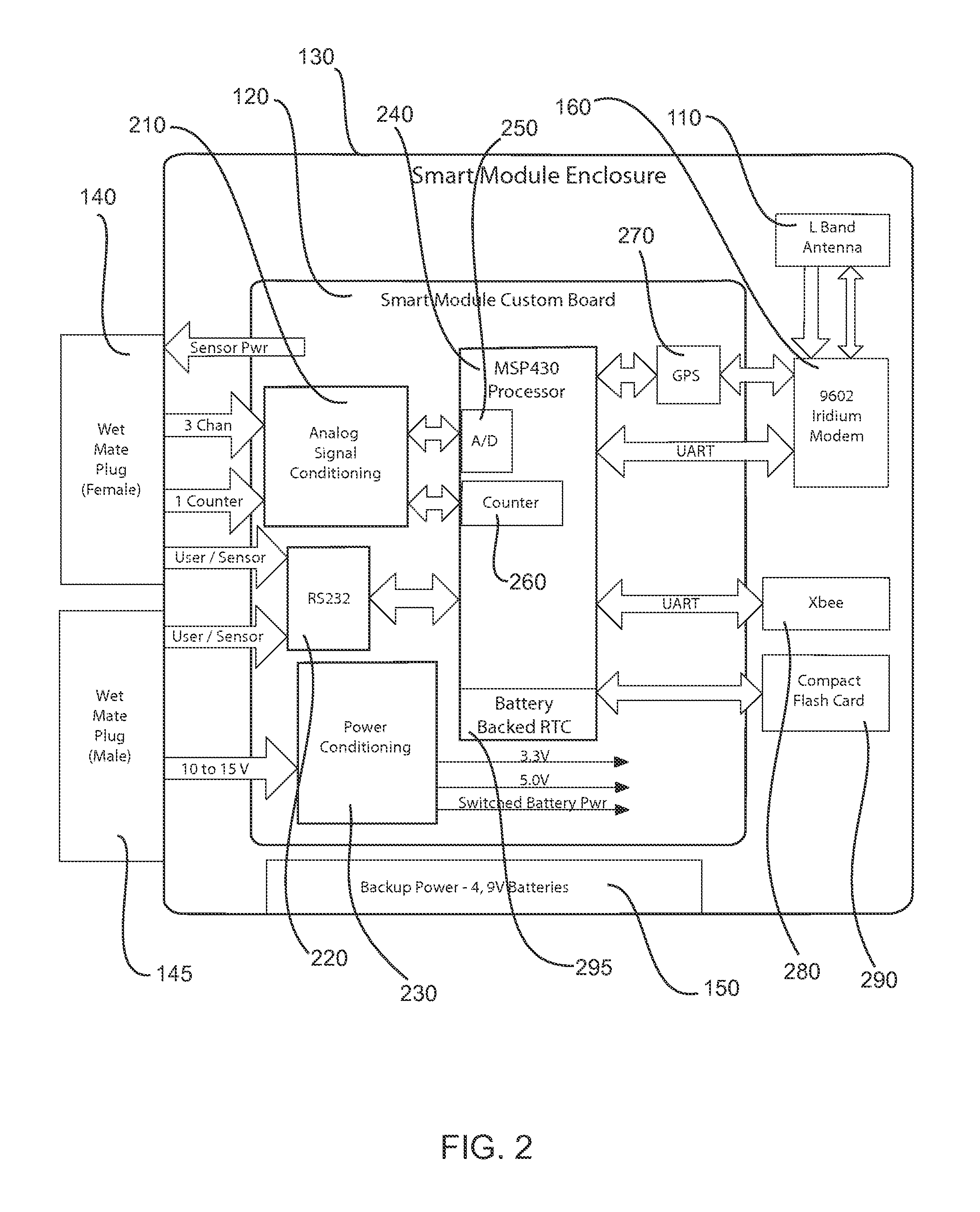
[0038]The following description and Figures describe the overall features of the smart module of the present invention. More detailed description of the invention may be found in the Appendices of Provisional U.S. Patent Application No. 61 / 921,298 filed on Dec. 27, 2013, and incorporated herein by reference. Appendix I contains the System Design Description for the Smart module of the present invention, while Appendix II includes the schematic diagrams for the Smart module of the present invention. Appendix III includes the source code for the software operating in the present invention. All three Appendices are incorporated herein by reference. Appendix III is also provided as an Appendix I to the present application.

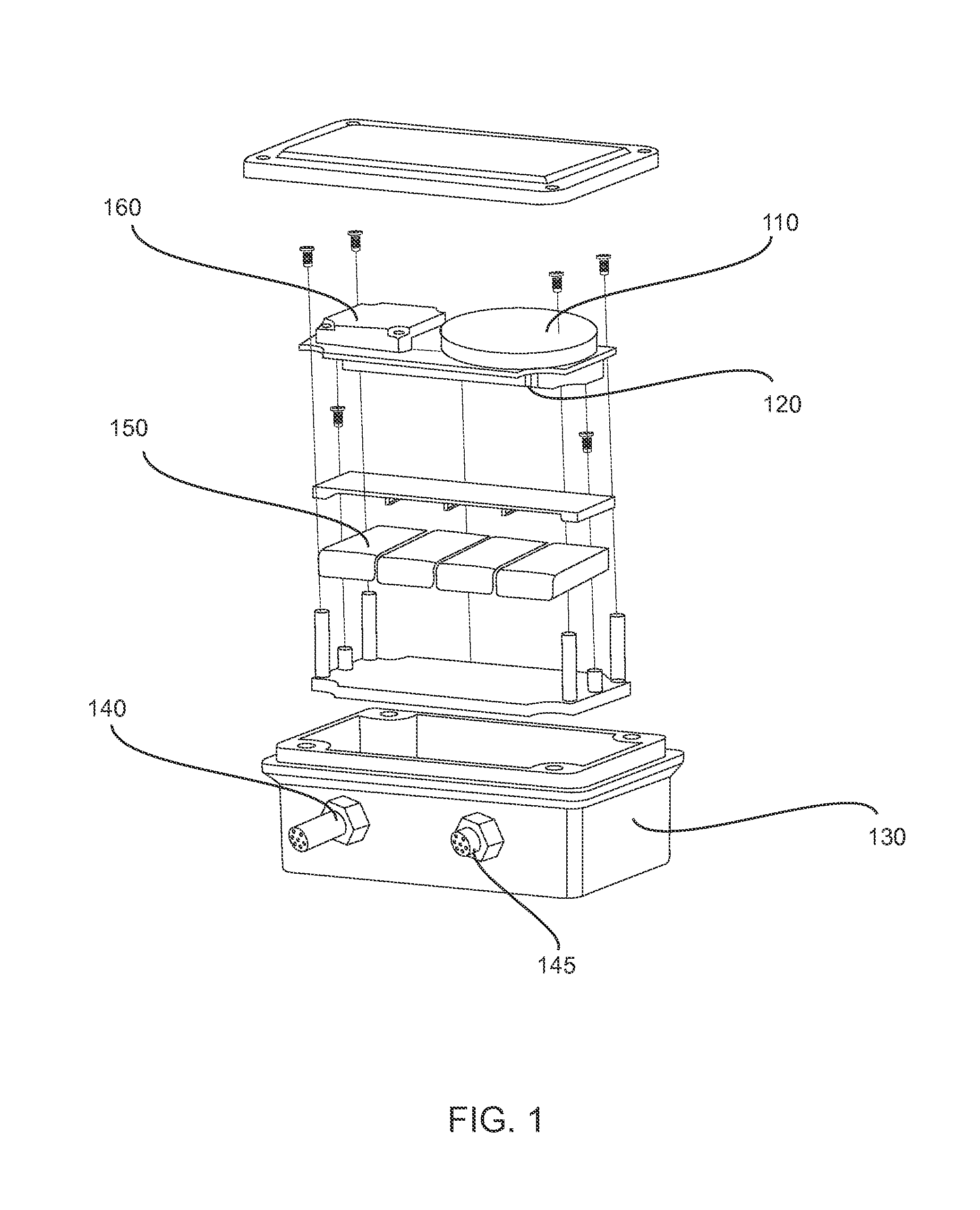
[0039]FIG. 1 is an exploded view of one embodiment of the apparatus of the present invention. Referring to FIG. 1, the present invention comprises a satellite transceiver 160, circuit board 120 including a GPS receiver, antenna 110, mass data storage device, short rang...


PUM


Abstract

The present invention is a unique combination and physical packaging of low power COTS electronics, real-time operating system, and custom firmware that relays data, messages, and GPS position through the Iridium Short Burst Data (SBD) satellite system. It is a data collector, processor, transmitter, location reporting, and data storage device that provides bi-directional satellite communications anywhere in the world. The combination is very low power and economical as compared to other devices. It can be used for many unattended remote data collection and reporting needs. The smart module may be used in measuring and reporting remote marine data for marine weather analysis, forecasts, and warnings.

Description

CROSS-REFERENCE TO RELATED APPLICATIONS[0001]The present application is a Continuation of U.S. patent application Ser. No. 14 / 147,676 filed on Jan. 6, 2014, and incorporated herein by reference; the present application also claims priority from Provisional U.S. Patent Application No. 61 / 921,298 filed on Dec. 27, 2013, and incorporated herein by reference.STATEMENT OF GOVERNMENT INTEREST[0002]The research that led to the development of the present invention was sponsored by the National Oceanic and Atmospheric Administration's (NOAA's) National Data Buoy Center (NDBC). NOAA is a part of the U.S. Department of Commerce, a component of the U.S. Federal government. The United States Government has certain rights in the present invention.FIELD OF THE INVENTION[0003]The present invention relates to a data collection and reporting system, particularly as used with data buoys and the like, for collecting environmental data. In particular, the present invention is directed toward a modular c...

Claims


Application Information

Patent Timeline
Patent Type & Authority Patents(United States)
IPC IPC(8): G06F19/00G01W1/00
CPCG01W2001/006G01W1/00Y02A90/10
Inventor RILEY, RODNEY, EUGENE
Owner THE UNITED STATES OF AMERICA AS REPRESENTED BY THE SECRETARY OF THE COMMERCE
Why Eureka
Try Eureka