Optical probe containing oxygen, temperature, and pressure sensors and monitoring and control systems containing the same

a technology of oxygen and temperature sensors, applied in the field of optical probes, can solve the problems of fuel tank penetration, fuel tank explosion potential upon ignition, and unplanned explosion of aircraft fuel tanks, and achieve the effects of improving accuracy, real-time oxygen concentration determination and calculation, and improving monitoring and control of oxygen levels

Inactive Publication Date: 2016-03-29
SUSKO KENNETH
View PDF29 Cites 10 Cited by
  • Summary
  • Abstract
  • Description
  • Claims
  • Application Information

AI Technical Summary

Benefits of technology

[0038]Because each of the sensors is located at the probe tip, data on oxygen concentration, temperature, and pressure are obtained at that location, providing a more accurate, real time, in situ determination and calculation of oxygen concentration, and therefore better monitoring and control of the level of oxygen in the space being monitored. Moreover, because no sample removal is required and data acquisition occurs within the space being monitored, accuracy is also increased. For example, embodiments of the probe and system described herein provide a sensor dynamic range of oxygen concentration ranging from 0% (total inertness) to 25% (in excess of air), with a resolution of 0.1% and an accuracy of 0.5% O2, and a sensor response time of a few seconds.
[0039]The use of fiber optics, rather than electronics, to gather and transmit data decreases the risk of an unanticipated ignition source as compared to electronic systems, because it is not the source of electrical or electrostatic sparks, does not produce a current, and is not otherwise an ignition source. Moreover, the probe and systems described herein is not affected chemically, physically, or functionally by exposure to liquid or vaporized fuel, which decreases the risk of adverse affects by contact with hydrocarbons (e.g. adverse interactions between aircraft fuel and galvanic cell membranes), and eliminates the need for heating resulting from the use of zirconium electrochemical cells, as well as eliminates any consumption of oxygen to operate the system. Moreover, the systems described herein are expected to require less frequent calibration, and to be less susceptible to interferences (such as EMI interference) than existing technologies. Embodiments of the probe described herein can be multiplexed to a single control unit, allowing multiple locations in a space to be monitored simultaneously.
[0040]Embodiments of the probe described herein are resistant to hydrocarbon exposure, resistant to the effects of thermal shock and pressure changes experience, e.g., during flight. For example, embodiments of the probe and system described herein can operate over a temperature range of −50 to +80° C., and over a pressure range of ambient to +2 psi. The probe described herein allows the vehicle operator to confirm that inerting or fire suppression is occurring as needed and according to specifications, to determine the inertness of the space being monitored, and allows for a closed loop control of oxygen levels in the space being monitored. Moreover, the system is small, light weight, and compatible with automatic control systems onboard the vehicle.

Problems solved by technology

Since 1959, a number of aircraft fuel tanks have unexpectedly exploded.
The presence of both a flammable gas and the fuel / vapor mixture within the space creates the potential for an explosion within the fuel tank upon ignition.
The industry has responded with various methods and apparatuses, as discussed in Air Safety Week, Vol. 15 No. 16, Apr. 16, 2001, “Fatal Explosion Highlights Hazard of Flammable Vapors in Fuel Tanks.” In addition, recent combat experience with fixed wing and rotary aircraft suggests that fuel tanks are susceptible to penetration by hostile fire, and in particular by shrapnel and small arms fire, which creates both an ingress for oxygen and a potential ignition source.
Moreover, if lightning penetrates the wing or fuel tank of an aircraft as the result of a lightning strike, it can be a significant source of ignition, particularly in aircraft constructed using composite materials.
Nonetheless, the need to continuously fill the fuel tank with an inert gas and the attendant high costs associated therewith do not make this an attractive alternative for aircraft manufacturers.
However, temperatures and pressures within an enclosed space, such as fuel tanks in vehicles, can fluctuate over time depending on the outside temperature.
In addition, spatial fluctuations in temperature and pressure within the fuel tank can occur.
Moreover, these fluctuations can impact the ability of the monitoring and control electronics to accurately determine the oxygen level from the data obtained from the oxygen sensor.
However, these methods are not suitable for use in fuel tanks, as electrical current applied to the electrical resistance heaters may potentially ignite the fuel / vapor mixture within the tank, again making this an unattractive option for aircraft manufacturers.
An oxygen probe containing a temperature sensor has also been developed, but the absence of an integrated pressure sensor requires that the system use pressure information from the aircraft pitot tubes.
As a result, the pressure measurement from such systems is not accurate information about the ullage pressure in the vicinity of the probe, where the oxygen level is actually being measured.
However, there is typically no access to the cargo hold from the flight deck, and even if the fire suppression system is effective, temperature in the cargo hold may remain elevated for a considerable period of time.
As a result, with such a system there is limited ability of the flight crew to determine in the short term whether the fire suppression system has been successfully deployed and has been effective in controlling the fire.
Fire suppression in passenger compartments provides a particular challenge, requiring precise control of the type and amount of fire suppression gas introduced, so as to decrease oxygen available for combustion while maintaining sufficient oxygen for life support of the passengers.
However, the implementation of this system is not optimal, because of the lack of an appropriate sensing / control system.
Such an operation, however, incurs a significant fuel penalty.
The use of fiber optics, rather than electronics, to gather and transmit data decreases the risk of an unanticipated ignition source as compared to electronic systems, because it is not the source of electrical or electrostatic sparks, does not produce a current, and is not otherwise an ignition source.

Method used


Image

  • Optical probe containing oxygen, temperature, and pressure sensors and monitoring and control systems containing the same
  • Optical probe containing oxygen, temperature, and pressure sensors and monitoring and control systems containing the same
  • Optical probe containing oxygen, temperature, and pressure sensors and monitoring and control systems containing the same

Examples


Embodiment Construction

[0047]As used herein, the term “about” in connection with a numerical value or range of numerical values denotes somewhat above and somewhat below the stated numerical value, to a maximum deviation of ±10%.

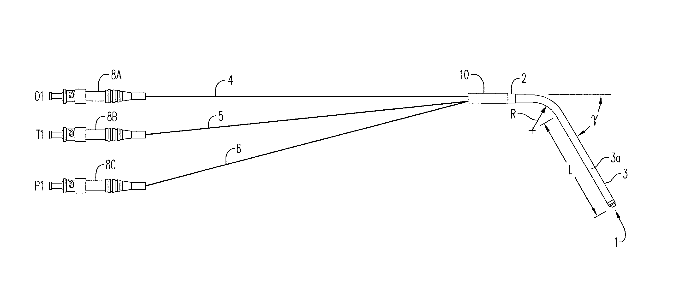
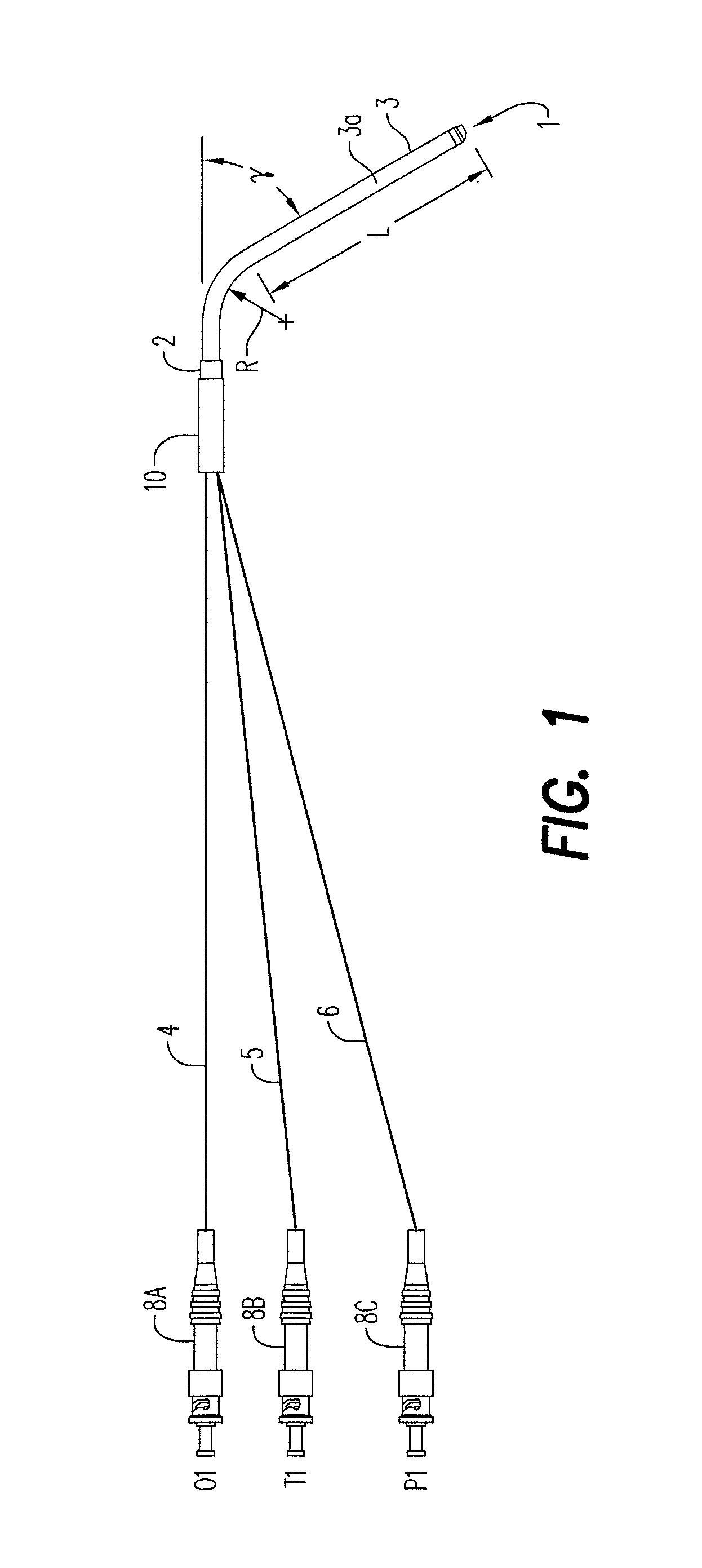
[0048]A particular embodiment of an integrated oxygen, temperature, and pressure probe is shown schematically in FIG. 1. Probe tip 1 is disposed at one end of probe tube 3. At the other end of probe tube 3 is disposed probe cover 2, adjacent to heat shrink tube 10. The probe tip 1 contains an oxygen sensor, a temperature sensor, and a pressure sensor, all connected to optical fibers (4, 5, and 6) (e.g., 1000-1100 micron fiber is generally suitable, however other fiber sizes can be used) enclosed within a polymeric tube (e.g., PTFE tube). In the illustrated embodiment, each optical fiber is connected to an optical connector (8A, 8B, and 8C) suitable for connection to an optoelectronic monitoring and / or control system (not shown). FIG. 1 provides representative dimensions with respe...


PUM

PropertyMeasurementUnit
pressureaaaaaaaaaa
temperatureaaaaaaaaaa
sizesaaaaaaaaaa

Abstract

A probe for measuring oxygen, temperature, and pressure in a space to be monitored, comprising: a housing, comprising a thermally conductive material; an oxygen sensor disposed within the housing, comprising: a first end having coated thereon a coating which fluoresces at a fluorescent frequency when exposed to light having an excitation frequency in the absence of associated oxygen, and which undergoes a dampening of said fluorescence in the presence of associated oxygen; and a second end operatively connected to an optical fiber that extends through the housing; wherein the first end extends through the housing and is adapted to be exposed to the space to be monitored; a temperature sensor disposed within the housing adjacent to the thermally conductive material, comprising a fiber Bragg grating, or a semiconductor material, such as a GaAS material, wherein the temperature sensor does not extend through the housing and is not exposed to the space to be monitored; a pressure sensor disposed within the housing, comprising a fiber Bragg grating or a Fabry-Pérot white light interferometry sensor having a first end which extends through the housing and is adapted to be exposed to the space to be monitored.

Description

[0001]This application is a continuation-in-part of, and claims benefit of the filing date of, U.S. application Ser. No. 13 / 279,994, filed Oct. 24, 2011, which claims benefit of U.S. Provisional Application No. 61 / 406,050, filed Oct. 22, 2010, the entire contents of which is incorporated herein by reference.BACKGROUND[0002]1. Field[0003]Disclosed herein is an optical probe containing integrated oxygen, temperature, and pressure sensors. The probe is particularly suitable for determining the concentration of oxygen, particularly the partial pressure of oxygen, in an enclosed space, such as a fuel tank, cargo hold, passenger compartment, or other space in a vehicle, such as an aircraft, ship, boat, land vehicle, or other military, commercial, or aerospace vessel.[0004]2. Description of Related Art[0005]Since 1959, a number of aircraft fuel tanks have unexpectedly exploded. Typically, the explosions occurred when an unknown ignition source ignited the fuel / vapor mixture in the fuel tan...

Claims


Application Information

Patent Timeline
Patent Type & Authority Patents(United States)
IPC IPC(8): G05D11/13B64D37/32G01L7/02G01K13/00G01D11/24G01K11/32G01N21/77G01N21/64G01D5/26
CPCG05D11/131B64D37/32G01D11/245G01K11/3206G01K13/00G01L7/026G01N21/643G01N21/7703G01D5/266G01D5/268G01N2021/6432G01N2021/772G01N2021/7786Y10T137/034Y10T137/2509
Inventor SUSKO, KENNETH
Owner SUSKO KENNETH
Why Eureka
Try Eureka