Check patentability & draft patents in minutes with Patsnap Eureka AI!

Rotation detection apparatus, motor control apparatus, motor driven apparatus, method of correcting rotation detection apparatus, and non-transitory computer-readable storage medium storing correction program

a technology of rotation detection and motor control, which is applied in the direction of process and machine control, process control, instruments, etc., can solve the problems of reducing the detection resolution of rotational speed and enabling the detection of a minute oscillation of rotational speed, and achieves high accuracy

Active Publication Date: 2016-04-05
CANON KK
View PDF2 Cites 0 Cited by
  • Summary
  • Abstract
  • Description
  • Claims
  • Application Information

AI Technical Summary

Benefits of technology

The present invention is about a rotation detection apparatus that can accurately detect the rotation of a motor. The apparatus includes a patterned member that rotates with the motor and produces detection signals that change as it rotates. The detection signals are then sent to a signal outputter. The apparatus also includes a correction system that uses pre-defined correction values to correct any errors in the detected signals caused by misalignment of the patterned member. This correction is done by a corrector that takes into account the reference position of the motor when it is in its original state. The invention also provides a motor control apparatus and a motor driven apparatus that includes the rotation detection apparatus. Overall, the invention allows for accurate detection of motor rotation and correction of any errors caused by misalignment of the patterned member.

Problems solved by technology

However, a manufacturing error in the rotatable member often shifts the arrangement of the pattern element portions from their designed positions, which is called an arrangement error.
However, the method disclosed in Japanese Patent Laid-open No. 10-229691 calculates the rotational speed without using neighboring pattern element portions, which degrades a detection resolution of the rotational speed and thereby disables detection of a minute oscillation of the rotational speed.

Method used


Image

  • Rotation detection apparatus, motor control apparatus, motor driven apparatus, method of correcting rotation detection apparatus, and non-transitory computer-readable storage medium storing correction program
  • Rotation detection apparatus, motor control apparatus, motor driven apparatus, method of correcting rotation detection apparatus, and non-transitory computer-readable storage medium storing correction program
  • Rotation detection apparatus, motor control apparatus, motor driven apparatus, method of correcting rotation detection apparatus, and non-transitory computer-readable storage medium storing correction program

Examples


Embodiment Construction

[0027]Exemplary embodiments of the present invention will be described below in detail with reference to the accompanied drawings.

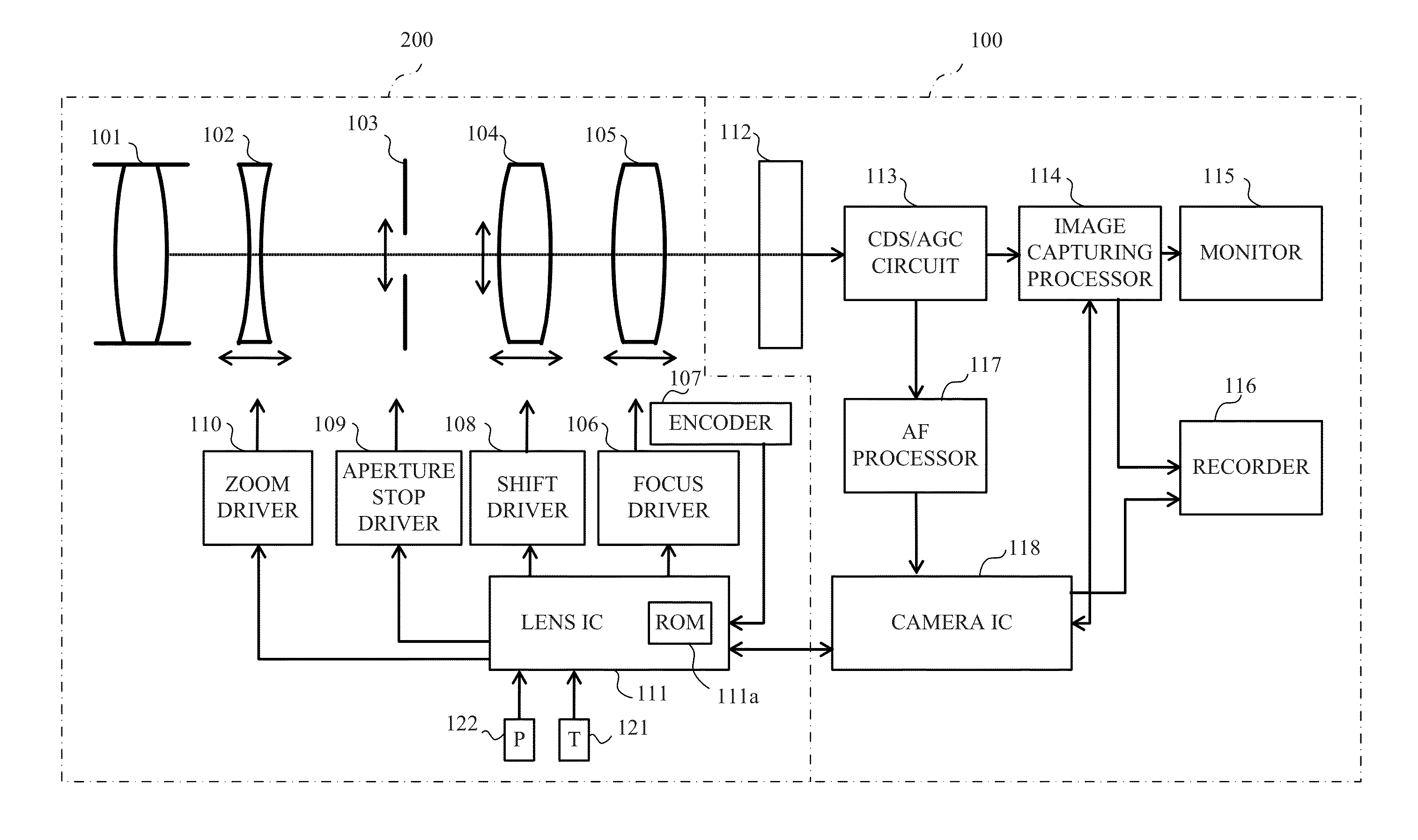
[0028]FIG. 1 illustrates a configuration of an interchangeable lens 200 as a motor driven apparatus including a magnetic rotary encoder that is an embodiment of the present invention. FIG. 1 also illustrates a configuration of a digital single-lens reflex camera 100 as an image pickup apparatus to which the interchangeable lens 200 is detachably attached. The image pickup apparatus may be a digital still camera, a digital video camera, a lens-integrated camera or a microscope.

[0029]The interchangeable lens 200 includes an image capturing optical system constituted by, in order from an object side, a fixed lens 101, a zoom lens 102, an aperture stop 103, an image-stabilizing lens 104 and a focus lens (optical element) 105. The zoom lens 102 is moved in a direction of an optical axis (hereinafter referred to as “an optical axis direction”) to perform variat...


PUM


Abstract

The rotation detection apparatus includes a rotatable member rotatable with rotation of a motor and having multiple pattern element portions in its rotational direction, a signal outputter to output a detection signal changing in response to rotation of the pattern element portions, and a memory storing correction values each provided for each of the pattern element portions and used to perform correction of an error in a relation between rotational positions of the rotatable member and the change of the detection signal. A corrector performs the correction with reference to a reference position of the rotatable member in an origin state where a driven member driven by the motor is located at its origin position and by using each of the correction values for each change of the detection signal when the rotatable member is rotated from the reference position.

Description

BACKGROUND OF THE INVENTION[0001]1. Field of the Invention[0002]The present invention relates to a rotation detection apparatus, which is also referred to as “a rotary encoder”, and particularly to a rotation detection apparatus used for control of a motor.[0003]2. Description of the Related Art[0004]Accurate control of a rotational amount or speed of a motor is made by a feedback control that feeds back an actual rotational amount or speed detected by a rotary encoder and controls the motor so that the detected rotational amount or speed becomes closer to a target rotational amount or speed. The rotary encoder includes a rotatable member that rotates with rotation of the motor, and a sensor that magnetically or optically detects a pattern for rotation detection (rotation detection pattern) provided to the rotatable member.[0005]The rotation detection pattern is formed by multiple pattern element portions which are S- and N-pole magnetized portions or light-transmissive / reflective a...

Claims


Application Information

Patent Timeline
Patent Type & Authority Patents(United States)
IPC IPC(8): G02B7/02G01D18/00G02B7/28G02B7/10G01D5/12G01D5/34G02B7/04G05B1/03G01D3/02G01D5/14G01D5/244G02B7/36H02P25/08H02P29/00
CPCG01D18/00G01D3/022G01D5/12G01D5/145G01D5/2449G01D5/34G02B7/04G02B7/10G02B7/102G02B7/28G05B1/03G02B7/365G05B2219/45178H04N23/672H04N23/673
Inventor YOSHIMUTA, JUNKI
Owner CANON KK
Features
  • R&D
  • Intellectual Property
  • Life Sciences
  • Materials
  • Tech Scout
  • Unparalleled Data Quality
  • Higher Quality Content
  • 60% Fewer Hallucinations
Learn More