Supercharge Your Innovation With Domain-Expert AI Agents!

Micro inverter of solar power system and method of operating the same

a solar power system and micro inverter technology, applied in photovoltaic energy generation, ac network circuit arrangement, dc-ac conversion without reversal, etc., can solve the problems of serious influence of partial shading and inelastic system expansion, and achieve the effect of increasing the output power value of the micro inverter

Active Publication Date: 2016-04-05
DELTA ELECTRONICS INC
View PDF23 Cites 0 Cited by
  • Summary
  • Abstract
  • Description
  • Claims
  • Application Information

AI Technical Summary

Benefits of technology

The present disclosure provides a micro inverter for a solar power system that can increase the output power of the system. The micro inverter includes a DC-to-DC converter, a DC-to-AC converter, a temperature sensor, and a microprocessor. The microprocessor receives the temperature detection signal and a power boosting signal, and acquires the output power value of the solar photovoltaic module based on the temperature detection signal when the power boosting signal is enabled. The microprocessor produces a first control signal to control the DC-to-DC converter and a second control signal to control the DC-to-AC converter, thus increasing the output power value of the micro inverter. The technical effect of this patent is to provide a more efficient and effective solar power system that can produce more energy.

Problems solved by technology

The research and development of alternative energy resources have become the major issue and key polity in many developed countries over the world since the two oil crises of the 1970s.
Because the solar energy has the pollution-free and public harm-free characteristics and is further inexhaustible in supply and always available for use, the solar energy has high potential applications and developments.
It is difficult to consider MPPT function for all in-series or in-parallel solar photovoltaic modules so that the utilization ratio of the solar photovoltaic modules is lower, the influence of the partial shading is serious, and the system expansion is inelastic.

Method used


Image

  • Micro inverter of solar power system and method of operating the same
  • Micro inverter of solar power system and method of operating the same
  • Micro inverter of solar power system and method of operating the same

Examples


first embodiment

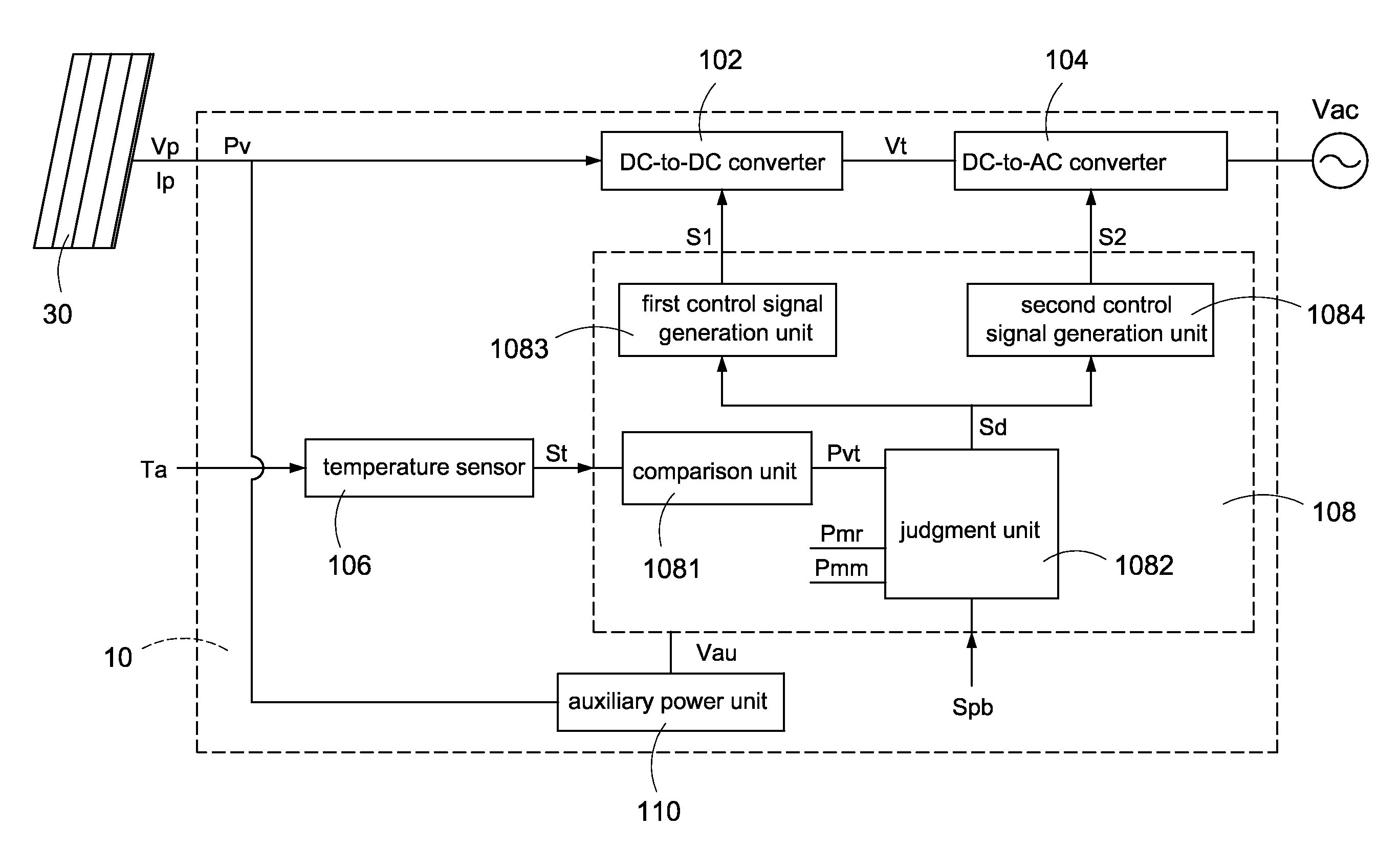
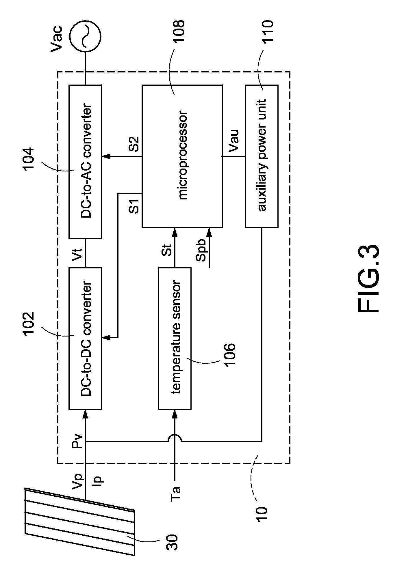
[0025]Reference is made to FIG. 3 which is a schematic circuit block diagram of a micro inverter of a solar power system according to the present disclosure. The solar power system provides a solar photovoltaic module output power Pv generated from a solar photovoltaic module 30, and the solar photovoltaic module output power Pv is converted into a micro inverter output power Pm by the micro inverter 10. The micro inverter 10 includes a DC-to-DC converter 102, a DC-to-AC converter 104, a temperature sensor 106, and a microprocessor 108. The DC-to-DC converter 102 receives a DC voltage Vp generated from the solar photovoltaic module 30, and converts the DC voltage Vp into a DC output voltage Vt. The DC-to-DC converter 102 is substantially a step-up converter to step up the DC voltage Vp. For a 60-cell solar photovoltaic module, the typical value of the DC voltage Vp is about 30 volts and the typical value of the DC output voltage Vt is about 300 volts. Hence, the DC-to-DC converter 1...

second embodiment

[0029]Reference is made to FIG. 5 which is a schematic circuit block diagram of the micro inverter of the solar power system according to the present disclosure. The solar power system provides a solar photovoltaic module output power Pv generated from a solar photovoltaic module 30, and the solar photovoltaic module output power Pv is converted into a micro inverter output power Pm by the micro inverter 20. The micro inverter 20 includes a DC-to-DC converter 202, a DC-to-AC converter 204, a voltage detector 206, a current detector 208, and a microprocessor 210. The DC-to-DC converter 202 receives a DC voltage Vp generated from the solar photovoltaic module 30, and converts the DC voltage Vp into a DC output voltage Vt. The DC-to-DC converter 202 is substantially a step-up converter to step up the DC voltage Vp. For a 60-cell solar photovoltaic module, the typical value of the DC voltage Vp is about 30 volts and the typical value of the DC output voltage Vt is about 300 volts. Hence...


PUM


Abstract

A method of operating a micro inverter of a solar power system includes following steps: First, an output power value of a solar photovoltaic module is acquired. Afterward, it is to judge whether the micro inverter executes a power boosting mode. If the power boosting mode is executed, a maximum output power of the micro inverter is boosted from a rated output power value to a maximum output power value. Finally, it is to judge whether the output power value of the solar photovoltaic module is greater than the maximum output power value. If YES, the maximum output power value is outputted from the micro inverter.

Description

BACKGROUND[0001]1. Technical Field[0002]The present disclosure relates generally to a micro inverter of a solar power system and a method of operating the same, and more particularly to a micro inverter with a power boosting function of a solar power system.[0003]2. Description of Related Art[0004]The research and development of alternative energy resources have become the major issue and key polity in many developed countries over the world since the two oil crises of the 1970s. In addition, the oil prices rise because the industrial development promotes the global economic growth and results in the rapid growth of the oil demand. Hence, environmental issues have received more attention recently, and more particularly to the effects of carbon dioxide on air pollution. In order to effectively reduce our dependence on oil as a source of energy, a variety of renewable resources, such as solar energy, wind energy, and so on, are researched and developed.[0005]Because the solar energy h...

Claims


Application Information

Patent Timeline
Patent Type & Authority Patents(United States)
IPC IPC(8): H02M7/44H02M1/32H02J3/38H02M1/00
CPCH02M7/44H02J3/383H02M1/32H02J3/385H02M2001/007H02J2300/26H02J2300/24H02J3/381Y02E10/56H02M1/007
Inventor LI, SHENG-HUA
Owner DELTA ELECTRONICS INC
Features
  • R&D
  • Intellectual Property
  • Life Sciences
  • Materials
  • Tech Scout
  • Unparalleled Data Quality
  • Higher Quality Content
  • 60% Fewer Hallucinations
Learn More